


B-8 37xxxE OM
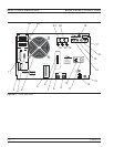
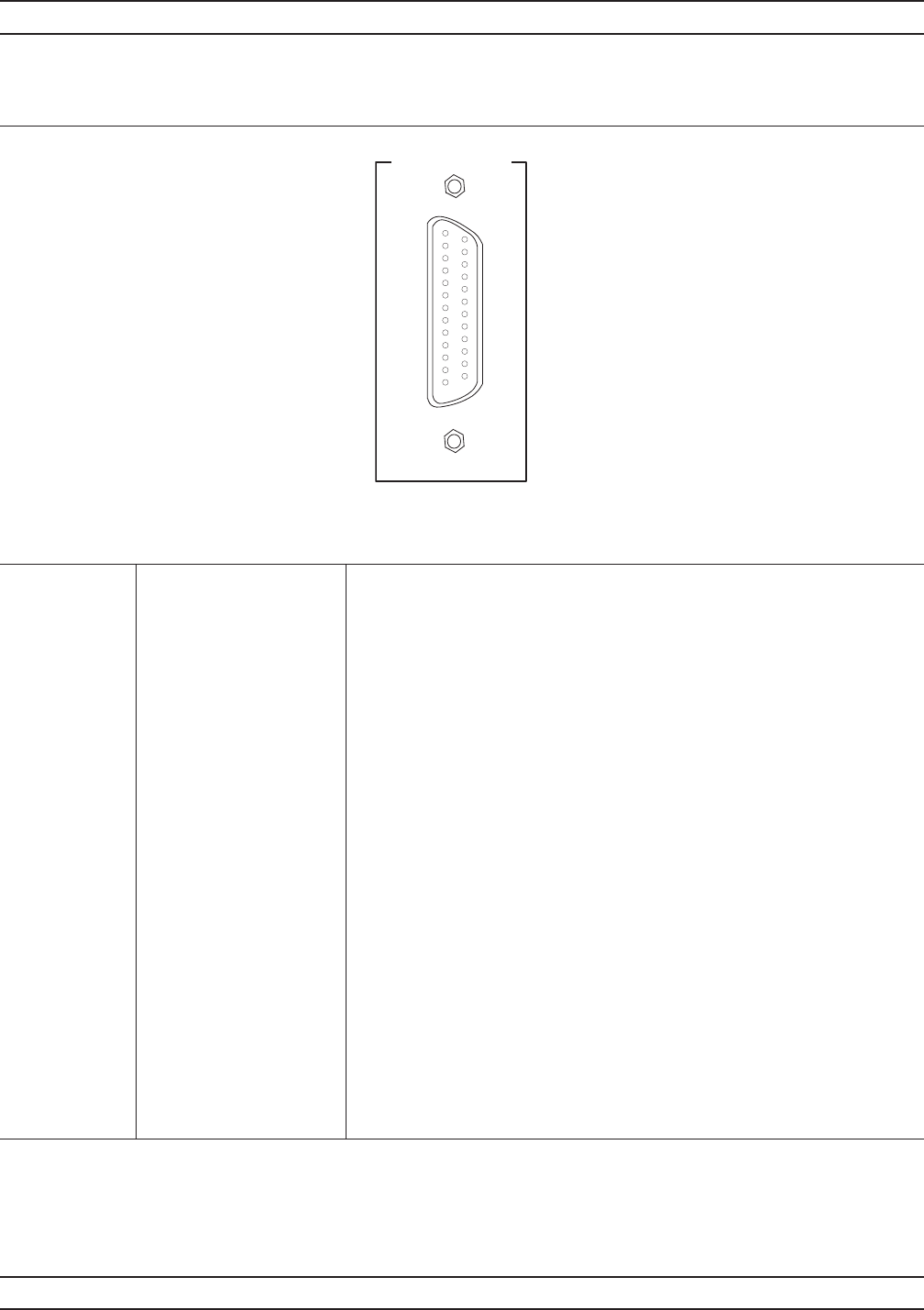
CONNECTOR PINOUT DIAGRAMS REAR PANEL CONNECTORS
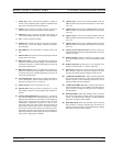
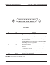
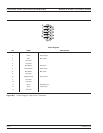
External I/O
1
2
3
4
5
6
7
8
9
10
11
12
13
14
15
16
17
18
19
20
21
22
23
24
25
Pinout Diagram
PIN NAME DESCRIPTION
1 Channel 1 Limit Signal indicating results of Channel 1 limit testing. User selectable TTL-high = Fail or
TTL-low = Fail.
2 Limit 1 Rtn Return for the Channel 1 limit signal
3 Channel 2 Limit Signal indicating results of Channel 2 limit testing. User selectable TTL-high = Fail or
TTL-low = Fail.
4 Limit 2 Rtn Return for the Channel 1 limit signal
5 Channel 3 Limit Signal indicating results of Channel 3 limit testing. User selectable TTL-high = Fail or
TTL-low = Fail.
6 Limit 3 Rtn Return for the Channel 3 limit signal
7 Channel 4Limit Signal indicating results of Channel 4 limittesting. User selectable TTL-high = Failor
TTL-low = Fail. Pins 7 is also used as the TTL handshake for external trigger mode.
TTL-high = VNA has compeleted a measurement and is ready for another trigger
8 Limit 4 Rtn Return for the Channel 4 limit signal or VNA measurement complete signal. Pin 8 is
also the return for pin 7.
9 Limit Fail Signal indicating failure in any channel limit testing. User selectable TTL-high = Fail
or TTL-low = Fail.
10 Spare
11 Spare
12 Limit Fail Rtn Return for the Limit Fail signal
13 Spare
14 Spare
15 Ext Dig In Allows an external signal to sync the 37xxxE measurements; TTL level
16 Dig In Rtn Return for External Dig In signal
Figure B-5. Pinout Diagram, External I/O Connector (1 of 2)