7-3 SLIDING TERMINATION Sliding terminations (loads) are the traditional Z
0
calibration-refer
-
ence devices for vector network analyzer calibration. When correctly
used and perfectly aligned, they can be more accurate than precision
fixed loads. However, sliding terminations have a 2 GHz (4 GHz for
V-Connector sliding loads) low-frequency limit and must be used with
a fixed load for full frequency-range coverage.
Sliding terminations consist of a connector, a long section of precision
transmission line, and a microwave load that is movable within the
transmission line. Pin depth—the relationship between the interface
positions of the outer and center conductors—is the most critical pa
-
rameter that you can control in a sliding termination. An example of
its criticality is that an incorrect pin depth of 0.001 inch can cause a
reflection return loss of 44 dB. Since you are usually calibrating to ac
-
curately measure a greater than 40 dB return loss, correct pin depth is
essential.
Since setting an accurate pin depth is so important, this discussion
centers on describing how to set the pin depth for male and female
sliding terminations. Calibration with the sliding termination is essen-
tially the same as described below for the broadband load.
The procedure below uses the Model 3652A Calibration Kit and its
17KF50 and 17K50 Sliding Terminations. Calibration is similar for the
Model 3650A SMA/3.5mm, Model 3651A GPC-7 and Model 3654D
V connector kits. For the 3651A, the procedure is simpler because the
GPC-7 connector is genderless, there are no male and female versions.
Procedure
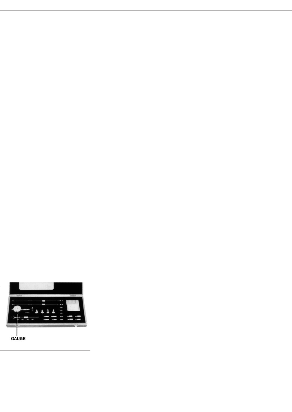
Step 1. Remove the Pin Depth Gauge from the kit, place it
on the bench top.
NOTE
The gauge is convertible between male and female. The
following procedure describes the zeroing process for the
female fitting. The procedure for the male fitting begins
with Step 16.
37xxxE OM 7-13
MEASUREMENT CALIBRATION SLIDING TERMINATION


