


Chapter 10
AutoCal
10-1 INTRODUCTION This chapter provides a general description of the AutoCal calibrators,
including specifications, setup, and the use of the associated software
and on-line documentation. This series has three models, as shown be
-
low. Throughout this manual, the term AutoCal will refer to the series.
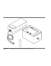
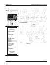
Individual models will be referred to by model number. Figure 10-1
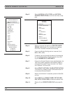
shows the AutoCal module and all of its attaching parts.
Model Switch Freq. Range Connector
36581NNF Electronic 40MHz-18 GHz N (Male)-N(Fem)
36581KKF Electronic 40MHz-20 GHz K(Male)-K(Fem)
36582KKF Mechanical 40MHz-40 GHz K(Male)-K(Fem)
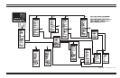
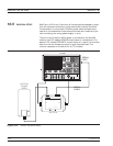
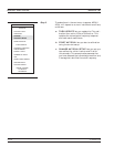
10-2 DESCRIPTION The AutoCal module provides an automatic system for fast, repeatable
high-quality calibrations of a Vector Network Analyzer (VNA). The
AutoCal module is connected between the VNA's test ports 1 and 2 to
perform the calibration. Refer to Figure 10-2 for a diagram of the
AutoCal connections.
The electronic AutoCal modules use solid state electronic switches to
exchange the internal calibration standards. Note that these units
have a lower frequency limit (18 and 20 GHz). The mechanical module
uses electro-mechanical actuators to exchange the standards and has
the highest frequency limit, but has a small non-repeatability error.
The mechanical module contains internal standards used to measure
port isolation; the electronic module does NOT contain isolation stan
-
dards and requires a manual operation to perform this measurement.
A standard serial RS-232 interface cable is used to connect the
AutoCal module to the 37xxxE. Power is supplied by a connecting ca
-
ble from a universal power supply (+5V, +15V, –15V for the electronic
modules; +5V, +24V for the mechanical modules). A power on-off
switch is not provided.
Test Port Cable Converters (Anritsu series 36583) are used during and
after the calibration process to establish the desired test port connec
-
tor type and sex.
37xxxE OM 10-3