


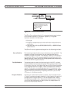
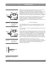
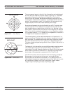

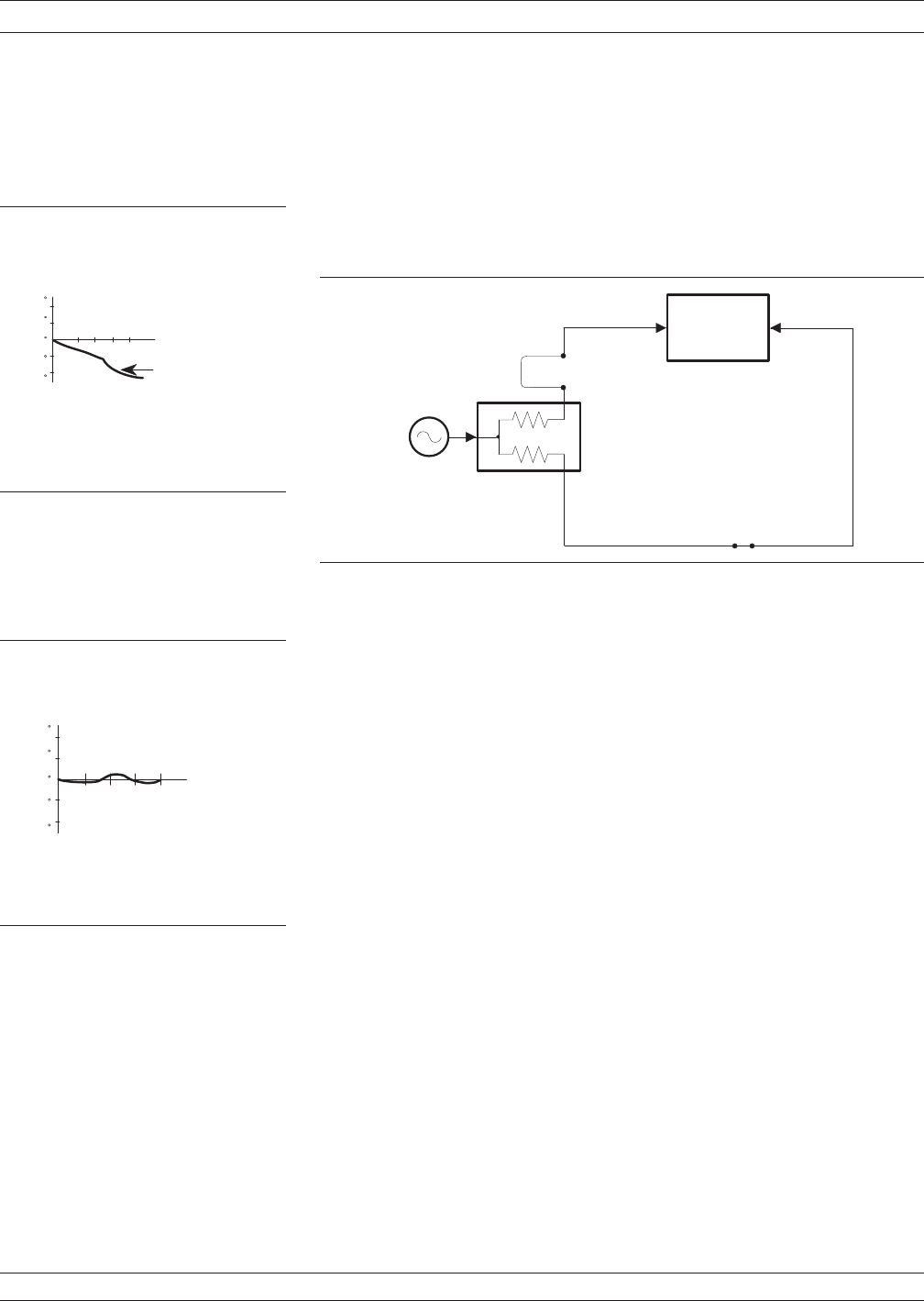
There are two ways of accomplishing this. The most obvious way is to
insert a length of line into the reference signal path to make both
paths of equal length (Figure 3-11, below). With perfect transmission
lines and a perfect splitter, we would then measure a constant phase
as we change the frequency. The problem using this approach is that
we must change the line length with each measurement setup.
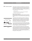
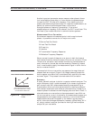
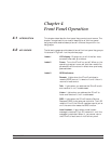
Another approach is to handle the path length difference in software.
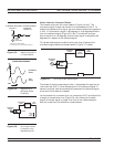
Figure 3-12 (left) displays the phase-vs.-frequency of a device. This
device has different effects on the output phase at different
frequencies. Because of these differences, we do not have a perfectly
linear phase response. We can easily detect this phase deviation by
compensating for the linear phase. The size of the phase difference
increases linearly with frequency so we can modify the phase display
to eliminate this delay.
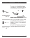
The 37xxxE offers automatic reference delay compensation with the
push of a button. Figure 3-13 (left) shows the resultant measurement
when we compensate path length. In a system application you can
usually correct for length differences; however, the residual phase
characteristics are critical.
NETWORK ANALYZERS NETWORK ANALYZERS, A PRIMER
3-8 37xxxE OM
PHASE
DETECTOR
REFERENCE
SIGNAL
SPLITTER
TEST
SIGNAL
MICROWAVE
SOURCE
BOTH LINE
LENGTHS
NOW EQUAL
Figure 3-11. Split Signal where Paths are of Equal Length
+180
+90
0
-90
-180
1.1
1.2
1.3
1.4
FREQUENCY,
GHz
MEASURED PHASE
SUBTRACT LINEAR
PHASE FROM
MEASURED PHASE
Figure 3-12. Phase Difference
Increases Linearly
with Frequency
0
1.1
1.2
1.3
1.4
FREQUENCY,
GHz
+2
+1
-1
-2
RESULTANT PHASE
Figure 3-13. Resultant Phase
with Path
Length