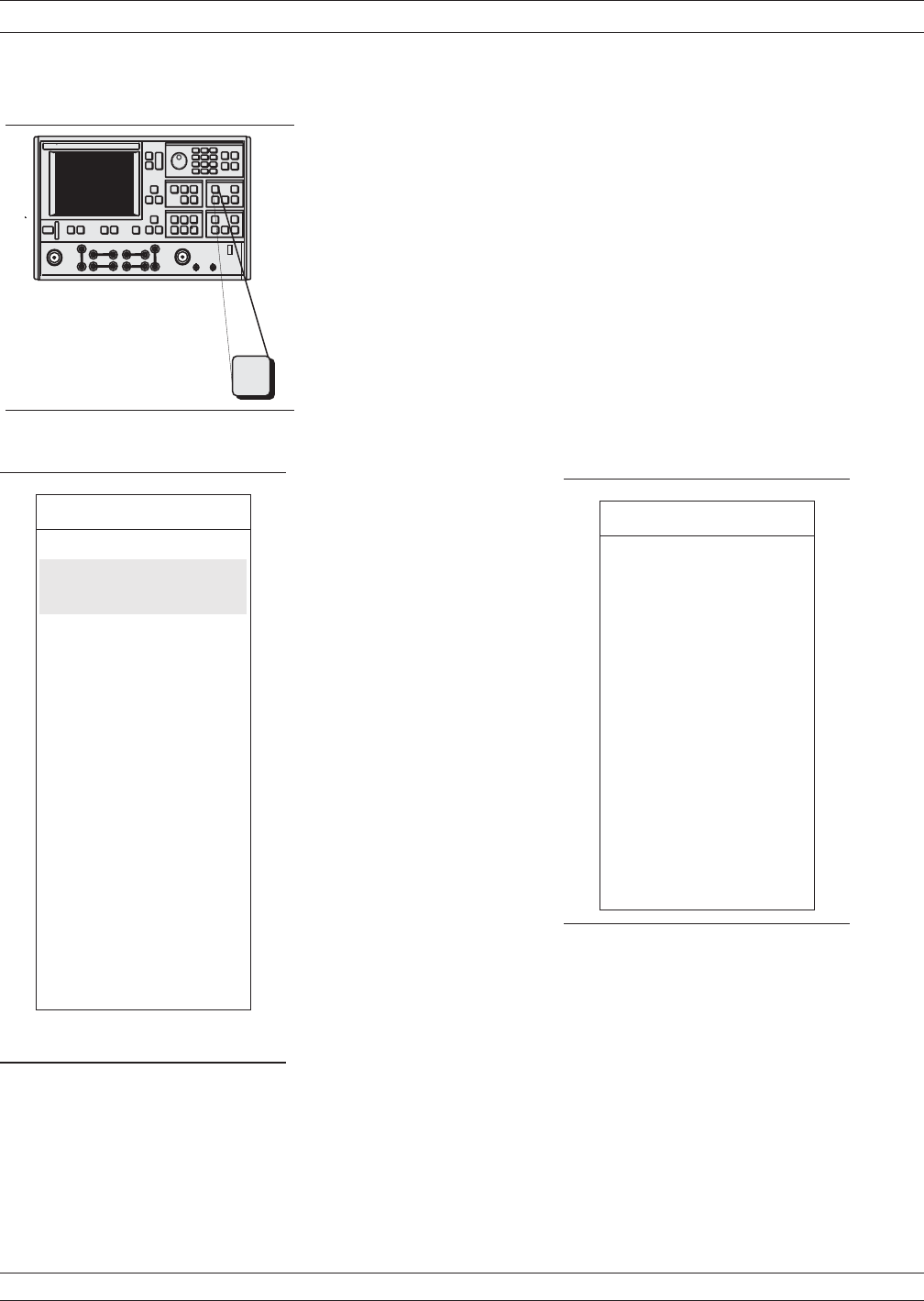
Step 13.
Press the Setup Menu key (top left), select POWER
CONTROL (bottom left) and increase the value
while observing compression in channel 3 (S
21
).
NOTE
The rotary knob or the keypad can be used
to set the POWER CONTROL value. In us
-
ing the rotary knob, the displayed value
does not change in real time with movement
of the control. Change occurs after the rota
-
tion of the knob is complete.
Step 14. Press the Marker Menu key again, and observe the
displayed Ch 3 trace and the marker values from the
displayed menu (below).
Step 15. The power linearity calibration, receiver calibration,
and DUT normalized data exists in volatile memory.
At this time, the data can be stored for subsequent
recall using the SAVE function.
NOTE
It is prudent to save this calibration; other
-
wise, it will be destroyed if you move any
-
where in the program except between this
calibration and the S-parameters menu.
GAIN COMPRESSION MEASUREMENTS
8-56 37xxxE OM
.
-
Measurement
Enhancement
Channels
Display
Setup
Menu
MENU SU2
MARKER 1
ALL DISPLAYED
CHANNELS
CH1-S11 USER
10.000000 GHz
12.06 dBm
CH 2 - S12
CH 3 - S21
10.000000 GHz
-0.992 dB
CH 4 - S21
MARKER TO MAX
MARKER TO MIN
MARKER READOUT
FUNCTIONS
PRESS <ENTER>
TO SELECT
MENU SU2
TEST SIGNALS
POWER CONTROL
5.47 dB
0 TO –20.00 dB
PORT 1 ATTN
0*10dB(0–70)
PORT 1 POWER
–1.53 dBm
PORT 2 ATTN
0 * 10 dB (0 –40)
CALIBRATE
FOR FLATNESS
(CAL EXISTS)
FLATNESS
CORRECTION
AT –11.53 dBm
PORT 2 POWER
0.00 dBm
EXIT APPLICATION
PRESS <ENTER>
TO SELECT
OR TURN ON/OFF


