


The lowpass step response displays the location of discontinuities as
well as information useful in determining the impedance (R, L, or C) of
each discontinuity. If you are familiar with time-domain reflectometry
(TDR) you may feel more comfortable with step response, as the dis
-
plays are similar.
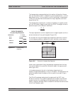
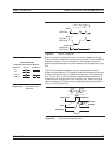
The lowpass step response for a resistive impedance is a positive level
shift for R>Z
0
and a negative level shift for R<Z
0
. The height of the re
-
sponse is equal to the reflection coefficient
r=
-
+
RZ
RZ
0
0
The step response for a shunt capacitance is a negative peak, and for a
series inductance it is a positive peak (Figure 9-3).
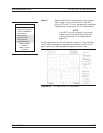
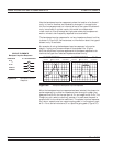
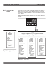
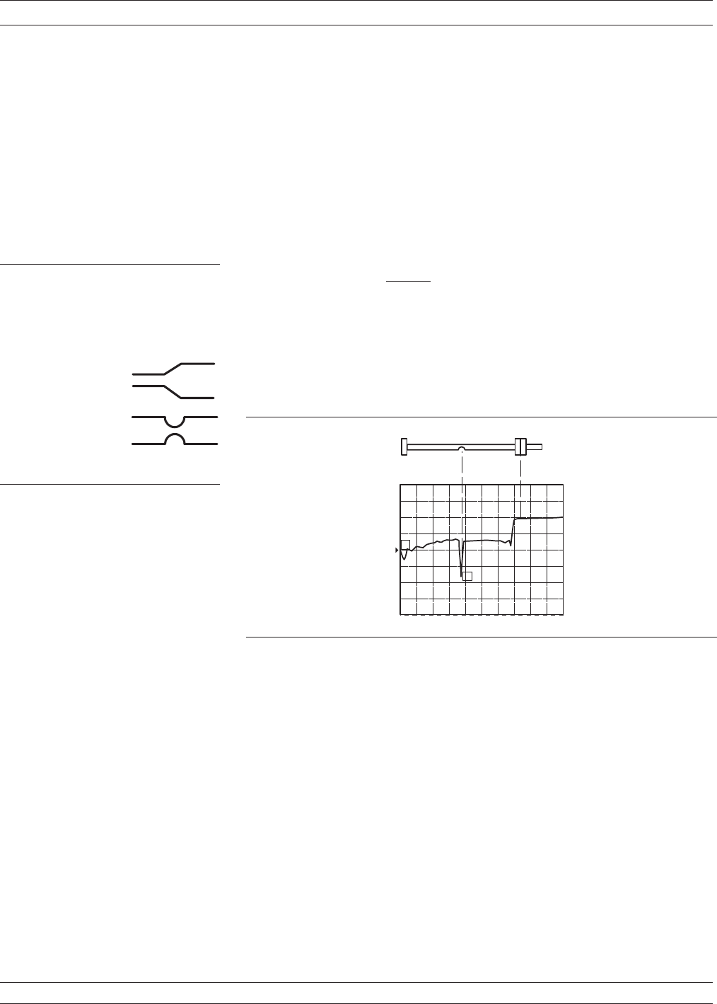
An example of using the lowpass step response is cable-fault location.
In the frequency domain a cable with a fault exhibits a much worse
match than a good cable. Using lowpass step response, both the loca
-
tion of the discontinuity and the information about its type are avail
-
able (Figure 9-4).
In the above example, the dip in the display shows the shunt-
capacitive response caused by a crimp in the cable. The response at the
end of the cable shows the step-up that is typical of an open (Figure
9-3, left).
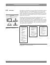
The 37xxxE bandpass mode gives the response of the DUT to an
RF-burst stimulus. Two types of response are available: impulse and
phasor-impulse. An advantage of the bandpass mode is that any fre
-
quency range can be used. Use this mode with devices that do not have
a dc or low-frequency path.
37xxxE OM 9-5
TIME DOMAIN TIME DOMAIN MEASUREMENTS
C I R C U I T E L E M E N T S
R > Z
O
S H U N T C
S E R I E S L
I M P E D A N C E
O
R < Z
1 1
S R E A L
L o w p a s s S t e p R e s p o n s e
Figure 9-3. Lowpass Step
Response
4 0 .0 0 0 c m
0 .0 0 0 m m
1
3
C A B L E
2
O P E N
Figure 9-4. Example of Lowpass Step Response