


LRL/LRM Calibration
(Microstrip)
Microstrip is a dispersive media. The 37xxxE applies dispersion
compensation during calibration for microstrip measurements.
Because the 37xxxE must know the specific microstrip parameters,
during the calibration procedure menus are available for entering the:
q
width of the strip
q
thickness of the substrate
q
substrate dielectric constant
q
effective dielectric constant Zc
q
characteristic impedance (reference)
When testing microstrip devices it is necessary to launch from coax to
microstrip. In production testing this launching must be temporary, so
that the device can easily be installed in and be removed from the fix
-
ture. The requirement for launching to 65 GHz is met by the Anritsu
Universal Test Fixture (UTF). The UTF provides accurate, repeatable
launch to substrates from 5 to 70 mils thick, and from 0.15 to 2 inches
long. Offset connections and right angles can be configured. DC bias
probes can be mounted to the UTF to inject bias onto the substrate.
UTF calibration/verification kits are available for alumina in 10 mil,
15 mil, and 25 mil microstrip, and for 25 mil coplanar waveguide. Al-
though a UTF is not essential, the following calibration procedures
presume its use.
Step 1. Select the desired LRL line substrates from the ap-
propriate microstrip calibration kit. When called for
in the calibration sequence, mount the LRL line sub-
strates on the UTF following the procedure given in
the 3680 OMM.
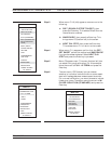
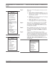
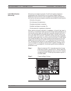
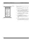
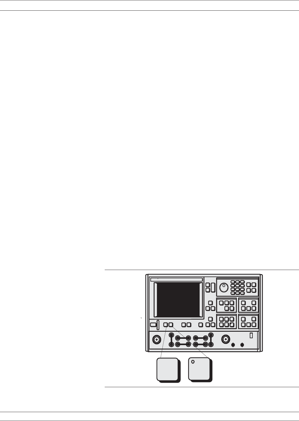
Step 2. Press the Begin Cal key.
37xxxE OM 7-37
MEASUREMENT CALIBRATION LRL/LRM CALIBRATION
.
-
Measurement
Enhancement
Channels
Display
Begin
Cal
Apply
Cal