Wide Dynamic Range Device - Filter
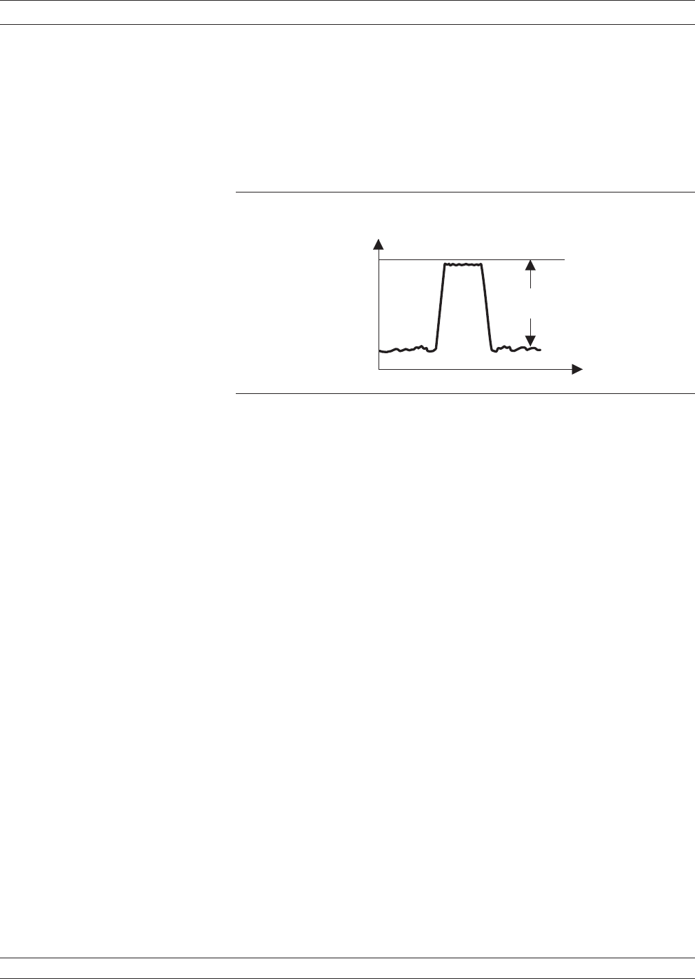
Since you do both low-insertion-loss and high- attenuation measure
-
ments simultaneously, use the maximum RF signal level and no atten
-
uation. Selecting the 1 kHz Video IF BW setting and 100 averages will
likely suffice for this kind of measurement (Figure 8-13).
High Gain Device - FET
This device has a typical 15 dB gain and requires an input level of
about –30 dBm. Set the Port 1 Source Attenuator to 30 dB. Since the
device RF output level is –15 dBm (–30 dBm + 15 dB[gain] = –15 dBm)
no attenuation is needed at Port 2.
Medium Power Device - Amplifier
Measure the small signal parameters of a 10 dB gain device that re
-
quires an input power level of 0 dBm. Here, Port 1 will have no attenu
-
ation. The device RF output level is 10 dBm. This level equals 10 dBm
(0 dBm + 10 dB[gain] = 10 dBm) into Port 2 and will cause compres
-
sion in the measurement. At least 10 dB of test attenuation will be
needed at Port 2, which will reduce the Port 2 RF level to 0 dB.
37xxxE OM 8-19
MEASUREMENTS LOW LEVEL AND GAIN
P A S S B A N D
< 1 d B
F R E Q U E N C Y
d B
B A N D P A S S F I L T E R
0 d B
S T O P B A N D
> 5 0 d B
S
2 1
Figure 8-13. Filter Measurements


