


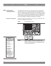
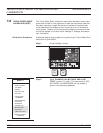

7-7 LRL/LRM CALIBRATION The LRL/LRM (line-reflect-line/line-reflect-match) calibration* feature
provides an enhanced capability for error compensation when making
measurements in coaxial, microstrip and waveguide transmission me
-
dia. Instead of using the standard Open, Short, and Load, the
LRL/LRM calibration method uses two lines and a reflection or match.
The difference in length between line 1 and line 2 creates the mea
-
surements necessary for the error solutions.
The LRL/LRM calibration technique uses the characteristic impedance
of a length of transmission line or a precision match as the calibration
standard. A full LRL/LRM calibration consists of two transmission line
measurements, a high reflection measurement, and an isolation
measurement. Using this technique full 12-term error correction can
be performed with the 37xxxE.
Three-line LRL/LRM calibration can also be selected. In a two-line
LRL measurement, the difference in length between line one and line
two is necessary for calibration but limits the frequency range to a 9:1
span. The use of three lines in the calibration extends the frequency
range to an 81:1 span. A combination of LRL and LRM can accomodate
any broadband measurement.
1. Through the use of LRL/LRM calibration and an external com-
puter, in conjunction with ANACAT software, multiple-level de-em-
bedding is possible. This calibration allows you to make semi-con-
ductor chip measurements up to 40 GHz with a single test fixture.
2. In addition, any non-coaxial transmission media, including mixed
media interconnects, can be accommodated. For example, a test de
-
vice with a waveguide input and a coplanar microstrip output can
be measured. Software automatically compensates for the
microstrip dispersion.
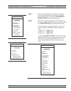
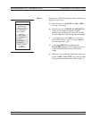
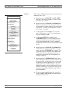
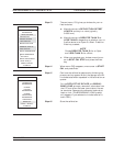
A detailed procedure for calibrating for a measurement using the
LRL/LRM method is provided in the following pages.
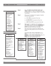
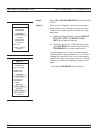
LRL/LRM CALIBRATION MEASUREMENT CALIBRATION
7-36 37xxxE OM
*LRM Calibration Method of Rhode & Scharwz, Germany