


37xxxE OM A-155
ALPHABETICAL LISTING M
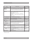
MENU DESCRIPTION GPIB COMMAND
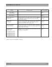
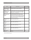
CH1—S11,USER None
+XXX.XXXX mm REF
+XXX.XXX dB OFFSET
+XXX.XX ° OFFSET
The constant offset for the channel is displayed. MK1? - MK6?
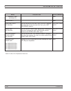
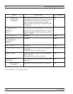
MARKER X
XXX.XXXXXXXXX GHz
MARKER TO MAX
MARKER TO MIN
The selected marker—that is, the one to which the cursor
points in menu M1—and its frequency, time, or distance
display here. This could be any one of the six available
markers: Marker 1 through Marker 6.
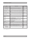
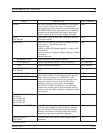
D(1-2)
XXX.XXXXXXXXX GHz
XX.XXX dB
XXX.XXX°
The marker numbers of the REF marker and the next
lowest-numbered selected marker appear between the
parentheses. This example assumes Marker 1 as the Ref
marker and Marker 2 as the next lowest-numbered selected
marker. The lines below display the difference frequency,
(or time/distance ) and trace value(s) between these two
markers on the active channel.
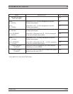
D(1-3)
XXX.XXXXXXXXX GHz
XX.XXX dB
XXX.XXX°
Same as above, except Marker 3 is the next
lowest-numbered selected marker.
D(1-4)
XXX.XXXXXXXXX GHz
XX.XXX dB
XXX.XXX°
Same as above, except Marker 4 is the next
lowest-numbered selected marker.
D(1-5)
XXX.XXXXXXXXX GHz
XX.XXX dB
XXX.XXX°
Same as above, except Marker 5 is the next
lowest-numbered selected marker.
D(1-6)
XXX.XXXXXXXXX GHz
XX.XXX dB
XXX.XXX°
Same as above, except Marker 6 is the next
lowest-numbered selected marker.
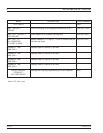
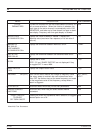
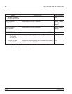
MARKER READOUT
FUNCTIONS
Calls menu M9, which lets you select readout marker
parameters.
None
Menu M5, Set DREF Marker Readout