


The measurement reference for the incident energy is the point at
which the device connects to the measurement system. We call this
point the reference plane. The incident energy at the reference plane is
defined as having a magnitude of 1 and a phase of 0 degrees. We estab-
lish this during the calibration.
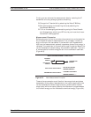
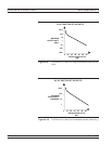
q The ratio of reflected and transmitted energy to the incident en-
ergy can be represented by a number of different measurements
and units, as shown below.
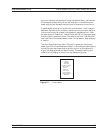
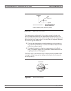
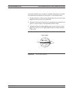
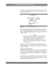
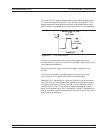
q The default display for reflection measurements is the Smith
chart. The default display for transmission measurements is the
Log Magnitude and Phase graph.
The Smith chart is a convenient way to display device impedance and
is a useful aid for the graphical design and analysis of microwave cir
-
cuits (Figure 8-5).
TRANSMISSION AND REFLECTION MEASUREMENTS
8-8 37xxxE OM
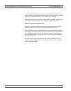
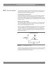
P H A S E
M A G N I T U D E
I M A G I N A R Y
R E A L
R E F L E C T I O N C O E F F I C I E N T =
R E F L E C T I O N ( M A G N I T U D E )
I N C I D E N T ( M A G N I T U D E )
P H A S E = IN C I D E N T ( P H A S E ) - R E F L E C T E D ( P H A S E )
Figure 8-4. Magnitude/Phase Vector
50
INDUCTIVE
CAPACITIVE
SMITH CHART
Ω
Figure 8-5 Smith Chart Display 1