Step 10. Press Save/Recall and save this de-embedded cali
-
bration to the SD Card or USB drive.
NOTE
Observe that the S11 graph displays the electrical return
loss (port match) of the modulator and S21 represents the
transfer function of the modulator. The bandwidth of the
modulator can be calculated from the S21 data by setting
the delta markers or using the marker search function to
find the 3 dB change in magnitude. The 3 dB bandwidth of
the modulator measured in this example is 24 GHz.
O/E Measurements Photo-diodes/photo-receivers convert an optical signal into an electri
-
cal signal. Bandwidth measurements can be made on a photo-di
-
ode/photo-receiver by stimulating its input with a modulated optical
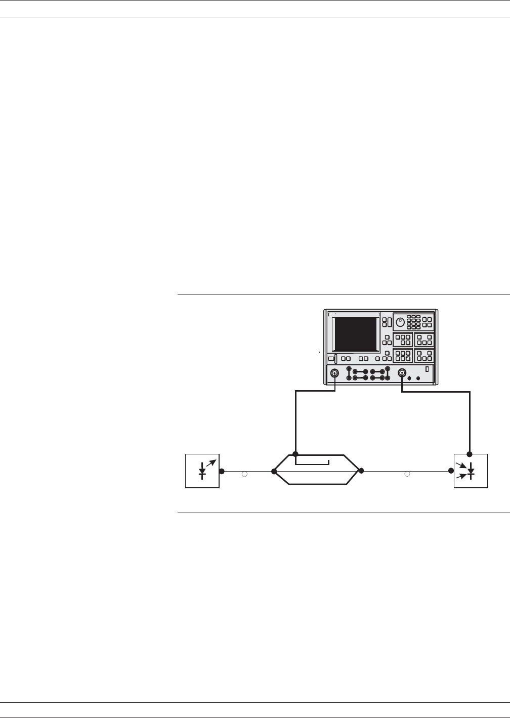
source and measuring the output signal. A laser and a characterized
modulator are required, in addition to the VNA, to make O/E measure
-
ments. See Figure 8-36, below, for the equipment set-up.
The O/E measurement application de-embeds the response of the mod
-
ulator transfer standard from a 12-term calibration to enable mea
-
surements of the photo-diode DUT.
O/E Measurement Procedure
The following procedure will explain ways of obtaining characteriza
-
tion data for a modulator and then how to use it to make an O/E mea
-
surement of a photo-receiver.
OPTICAL APPLICATION MEASUREMENTS
8-68 37xxxE OM
.
-
Measurement
Enhancement
Channels
Display
Laser
Source
Modulator Photo-diode
37xxxE
RF In
Port 1 Port 2
RF Out
Fiber
Fiber
Figure 8-36. O/E Measurement Set-up


