


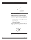
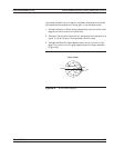
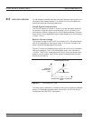
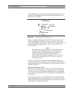
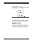

The detected signal is the vector sum of the desired signals, the noise
signals, and the leakage signals. These signals introduce an error or
uncertainty (Figure 8-8).
Some of the possible leakage paths for the 37xxxE are the transfer
switch, the frequency conversion module, and the DUT. The system
limits these leakages to greater than 100 dB. The 12-term error correc-
tion can reduce this leakage to better than 110 dB at 18 GHz and
90 dB at 40 GHz.
NOTE
We recommend using an isolation cell to decrease leakage
signals for sensitive measurements. For best results, in-
crease the default averaging value and decrease the de
-
fault IF bandwidth setting during calibration and
measurement. Using higher enhancement during the mea
-
surement than the calibration will not result in any accu
-
racy improvements.
The DUT connectors should have internally captivated center pins.
Those connectors which use external pins to captivate the center con
-
ductor should have silver loaded epoxy on the pins to reduce radiation
to better than 80 dB.
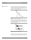
Signal-to-Noise-Power Ratio
The signal-to-noise-power ratio for each of the test or reference chan
-
nels is as shown. The “signal power” is the power level of the 80 kHz
IF signal at the internal synchronous detectors, and the “noise power”
is the total power contained within the bandwidth of the bandpass fil
-
ter at 80 kHz.
The uncertainty, or error, in a measurement is a function of the ampli
-
tude of leakage signals and of the noise level. The uncertainty in the
measurement of magnitude and phase of the S-parameters are calcula
-
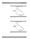
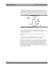
ble and shown in Figures 8-9 and 8-10.
37xxxE OM 8-13
MEASUREMENTS LOW LEVEL AND GAIN
D E T E C T E D O U T P U T S I G N A L
U N C E R T A I N T Y
N O I S E S I G N A L
A C T U A L S I G N A L
R E A L
M E A S U R E D
S I G N A L
L E A K A G E O R
F A L S E S I G N A L
I
M
A
G
I
N
A
R
Y
P H A S E E R R O R
Figure 8-8. Amplitude and Phase Uncertainty