NOTE
This step is not required for a successful
gain compression measurement; however,
calibrating the power from Port 1 (which is
what this step does) provides increased ac
-
curacy.
Prepare the power meter as described in the follow
-
ing instructions:
a. Preset, zero, and calibrate the power meter.
b. Set power meter offset, if required.
c. Connect the power meter to the dedicated GPIB
interface and the power sensor to the test port.
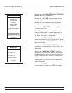
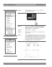
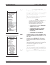
d. Select <START LINEAR POWER CALIBRA
-
TION>.
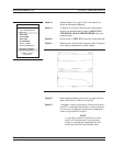
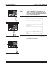
Connect the power sensor to Port 1.
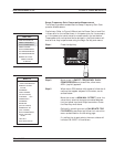
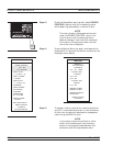
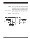
Set the number of power calibration points.
If, in a previous menu, data points had been set to
401 points, entering 8 provides 50 power points
(every 8th point); entering 4 provides 100 power
point (every 4th point)s, and entering 1 provides 401
power points. The VNA interpolates between power
calibration frequencies.
Enter a POWER TARGET value.
Make this value the same as resulting Port 1 power
value shown in Figure 8-28 (page 8-40). –25 dBm for
the example.
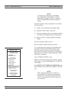
With START FLAT POWER CALIBRATION high
-
lighted (bottom left), press Enter to begin the calibra
-
tion.
NOTE
When the above calibration finishes, the
source power will have been accurately cali
-
brated. In the next step, this power calibra
-
tion will be transferred via the through line
to the receiver.
GAIN COMPRESSION MEASUREMENTS
8-52 37xxxE OM
MENU GC_SU8A
CALIBRATE FOR
FLAT PORT POWER
FORWARD
DIRECTION ONLY
101 POINTS
MEASURE 1 PWR
POINT EVERY
1 POINT(S)
POWER TARGET
–25.00 dBm
START FLAT
POWER CALIBRATION
PREVIOUS MENU
PRESS <ENTER>
TO SELECT
TURN KNOW TO
CHANGE NUMBER
OF POINTS


