


3-3 NETWORK ANALYZERS We will begin this discussion with a subject familiar to most Anritsu
customers: scalar network analysis. After showing comparisons, we
will proceed to the fundamentals of network analyzer terminology and
techniques. This discussion serves as an introduction to topics pre
-
sented in greater detail later in this section. This discussion will touch
on new concepts that include the following:
q
Reference Delay
q
S-parameters: what they are and how they are displayed
q
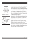
Complex Impedance and Smith Charts
Scalar Analyzer Comparison
Network Analyzers do everything that scalar analyzers do except dis
-
play absolute power. In addition, they add the ability to measure the
phase characteristics of microwave devices and allow greater dynamic
range.
If all a Network Analyzer added was the capability for measuring
phase characteristics, its usefulness would be limited. While phase
measurements are important in themselves, it is the availability of
this phase information that unlocks many new features for complex
measurements. These features include Smith Charts, Time Domain,
and Group Delay. Phase information also allows greater accuracy
through vector error correction of the measured signal.
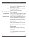
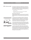
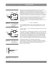
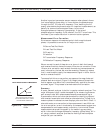
First, let us look at scalar network analyzers (SNAs). SNAs measure
microwave signals by converting them to a DC voltage using a diode
detector (Figure 3-3). This DC voltage is proportional to the magnitude
of the incoming signal. The detection process, however, ignores any
information regarding the phase of the microwave signal.
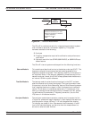
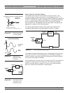
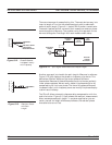
In a network analyzer, access is needed to both the magnitude and
phase of a microwave signal. There are several different ways to per
-
form the measurement. The method Anritsu employs (called Harmonic
Sampling or Harmonic Mixing) is to down-convert the signal to a lower
intermediate frequency (IF). This signal can then be measured directly
by a tuned receiver. The tuned receiver approach gives the system
greater dynamic range. The system is also much less sensitive to inter
-
fering signals, including harmonics.
37xxxE OM 3-5
NETWORK ANALYZERS, A PRIMER NETWORK ANALYZERS
SCALAR NETWORK ANALYZERS
MICROWAVE
SIGNAL
MICROWAVE
DETECTOR
DETECTOR
OUTPUT
VOLTAGE
DETECTOR OUTPUT VOLTAGE IS PROPORTIONAL
TO SIGNAL AMPLITUDE.
Figure 3-3. Scalar Analyzer
Detection