


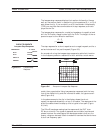
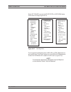
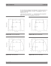
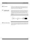
Next, let us look at a complex circuit. A resistive impedance change
R<Z
0
and a shunt capacitance and series inductance. These impedance
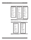
changes are shown in the time domain for the lowpass-impulse re-
sponse, lowpass-step response, and bandpass-impulse response (Figure
9-8).
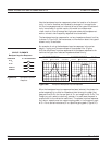
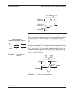
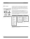
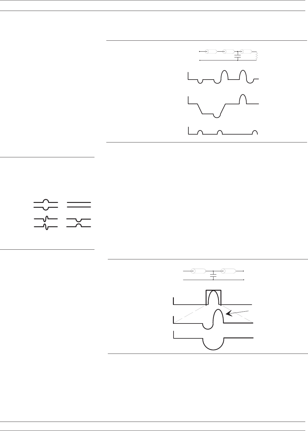
The 37xxxE processes bandpass-impulse-response data to obtain
phasor-impulse response. This becomes most advantageous where both
a reactive reflection and an impedance change occur at the same loca-
tion. The real part of the time-domain response shows the location of
impedance level changes, while the imaginary part shows the type of
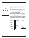
reactive discontinuity. Phasor-impulse response displays one disconti-
nuity at a time (Figure 9-9).
37xxxE OM 9-7
TIME DOMAIN TIME DOMAIN MEASUREMENTS
R E A L S
1 1
M A G N IT U D E S
1 1
R E A L S
1 1
5 c m1 0 c m
1 0 c m
5 0
9
2 0
9
5 0
9
L O W P A S S
R E S P O N S E
L O W P A S S
R E S P O N S E
B A N D P A S S
R E S P O N S E
Figure 9-7. Complex Impedances
C I R C U I T E L E M E N T S
B a n d p a s s - P h a s o r I m p u l s e R e s p o n s e
R > Z
O
S H U N T C
S E R IE S L
I M P E D A N C E
1 1
R E A L S
I M A G I N A R Y S
1 1
O
R < Z
Figure 9-8. Bandpass Phasor
Response
M A G N I T U D E
R E A L
I M A G I N A R Y
S P A N
B A N D P A S S
C
5 c m
1 0 c m
2 0
9
5 0
9
I M P U L S E
P H A S O R
Figure 9-9. Phasor-Impulse Response Data