Use the bandpass-impulse response to show the location of a disconti
-
nuity in time or distance, as indicated by changes in its magnitude.
Unlike the lowpass mode, no information as to the type of the disconti
-
nuity is available. A typical use for this mode is to measure de
-
vices—such as, filters, waveguide, high-pass networks, bandpass net
-
works—where a low-frequency response is not available.
The bandpass-impulse response for various impedance discontinuities
is shown in Figure 9-5. As we can see, no information about the type of
discontinuity is available.
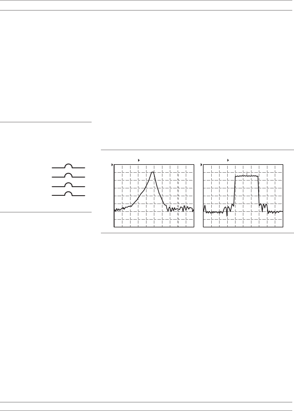
An example of using the bandpass-impulse response, is the pulse
height, ringing, and pulse envelope of a bandpass filter (Figure
9-6).Use the phasor-impulse response with bandpass response to de
-
termine the type of an isolated impedance discontinuity.
After the bandpass-impulse response has been isolated, the phasor-im
-
pulse response for a resistive-impedance-level change is a peak that
goes positive (R>Z
0
) for the real part of S
11
and negative for R<Z
0
. The
imaginary part remains relatively constant. In each case the peak is
proportional to the reflection coefficient. The phasor-impulse response
for a shunt capacitance is a negative-going peak in the imaginary part
of S
11
. For a series inductance, it is a positive going peak (Figure 9-7).
TIME DOMAIN MEASUREMENTS TIME DOMAIN
9-6 37xxxE OM
C I R C U I T E L E M E N T S
R > Z
O
S H U N T C
S E R I E S L
I M P E D A N C E
B a n d p a s s I m p u l s e R e s p o n s e
O
R < Z
1 1
S L O G M A G N I T U D E
Figure 9-5. Bandpass Impulse
Response
L O G M A G .
0 . 5 0 0 0
G H z
4 . 0 0 0 0
R E F = 2 0 .0 0 0 d B 2 0 . 0 0 0 d B /D IV
L O G M A G .
0 . 5 0 0 0 G H z
4 . 0 0 0 0
1 0 .0 0 0 d B / D I VR E F = 3 0 . 0 0 0 d B
B P w / G
S 2 1 F O R W A R D T R A N S M I S S IO N S 2 1 F O R W A R D T R A N S M IS S I O N
Figure 9-6. Example of Bandpass-Impulse Response


