


Chapter 9
Time Domain
9-1 INTRODUCTION This chapter describes the optional Time Domain feature.
9-2 TIME DOMAIN
MEASUREMENTS
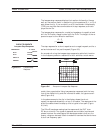
The Option 2, Time Domain feature provides a useful measurement
tool for determining the location of impedance discontinuities. Some
typical applications are identifying and analyzing circuit elements, iso
-
lating and analyzing a desired response, locating faults in cables, and
measuring antennas.
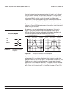
The relationship between the frequency-domain response and the
time-domain response of a network is described mathematically by the
Fourier transform.
The 37xxxE makes measurements in the frequency domain then calcu-
lates the inverse Fourier transform to give the time-domain response.
The time-domain response is displayed as a function of time (or dis-
tance). This computational technique benefits from the wide dynamic
range and the error correction of the frequency-domain data.
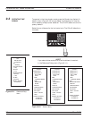
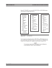
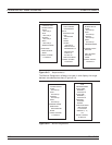
Let us examine the time-domain capabilities. Two measurement
modes are available: lowpass and bandpass.
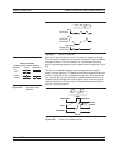
We use the lowpass mode with devices that have a dc or low-frequency
response. In the lowpass mode two responses to the device-under-test
(DUT) are available: impulse or step response.
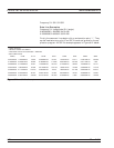
The frequencies used for the test must be harmonically related (inte
-
ger multiples) to the start frequency. The simplest way to calculate
this relationship is to divide the highest frequency in the calibration
by 1600 (the default number-of-points available); this is the start fre
-
quency. For example, if the highest frequency is 40 GHz, the calculated
start frequency is 0.025 GHz (40/1600). If the highest frequency is 65
GHz, the calculated start frequency is 0.040625 GHz (65/1600).
37xxxE OM 9-3