


Receiver Mode Block
Diagram
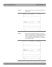
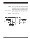
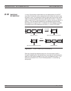
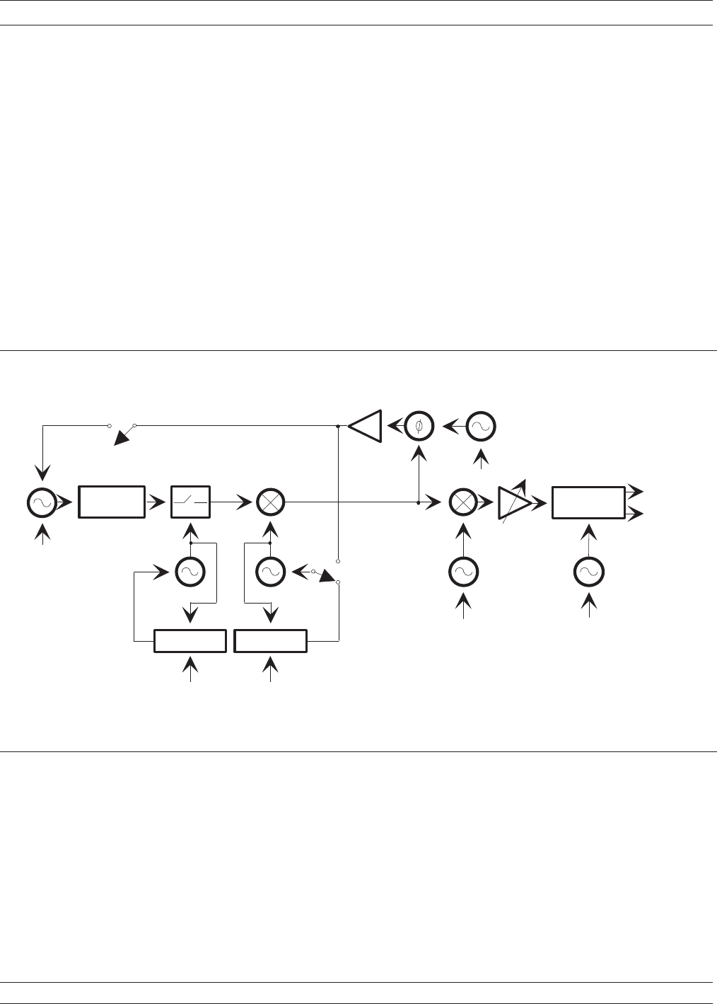
The block diagram shown in Figure 8-31 shows how the system is con
-
figured for all of the possible modes of operation. With the switches set
as shown, the system operates in the Set-On mode. LO1 and LO2 are
pre-set to allow only a prescribed signal to be detected by the synchro
-
nous detector. With the switch in SOURCE LOCK position the system
is operating in the internal source-lock mode. With the switch in the
TRACKING position, the system is in the synthesizer tracking mode.
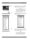
Receiver Mode Menus The menus associated with the Receiver Mode are described in the al
-
phabetical listing (Appendix A) under their call sign: RCV1, RCV2,
RCV3, etc.
Procedure, Receiver Mode
Operation
A detailed procedure for operation using the Receiver Mode option is
provided in the following pages.
37xxxE OM 8-59
MEASUREMENTS RECEIVER MODE
SOURCE LOCK
ANALOG LOCK SIGNAL
SAMPLER
1ST L.O. 2ND L.O.
TRACKING
SET ON
10 MHz
(SYNTHESIZER)
TRACKING
SOURCE LOCK/
SET ON
10 MHz
10 MHz
10 MHz
REAL
IMAGINARY
2.5 MHz
3RD L.O.
2.42 MHz
4TH L.O.
80 KHz
10 MHz 10 MHz
SYNCHRONOUS
DETECTOR
PLLPLL
RF MEASURE
CIRCUIT
Figure 8-31. 37xxxE Phase Lock Modes