


Chapter 3
Network Analyzers,
A Primer
3-1 INTRODUCTION This section provides front panel operating and measurement applica
-
tion information and data. It includes discussions on the following top
-
ics:
q
System description
q
General discussion about network analyzers
q
Basic measurements and how to make them
q Error correction
q General discussion on test sets
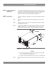
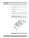
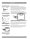
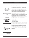
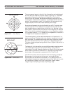
3-2 GENERAL DESCRIPTION The Model 37xxxE Vector Network Analyzer System measures the
magnitude and phase characteristics of networks, amplifiers,
attenuators, and antennas. It compares the incident signal that leaves
the analyzer with either the signal that is transmitted through the
test device or the signal that is reflected from its input. Figure 3-1 and
Figure 3-2 illustrate the types of measurements that the 37xxxE can
make.
37xxxE OM 3-3
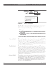
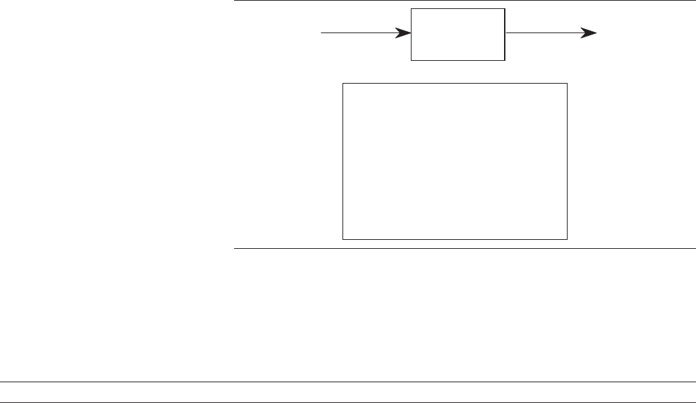
TRANSMITTEDINCIDENT
TEST
DEVICE
Gain (dB)
Insertion Loss (dB)
Insertion Phase (degrees)
Transmission Coefficients (S12, S21)
Separation of Transmission
Components (Real and Imaginary)
Electrical Length (m)
Electrical Delay (s)
Deviation from Linear Phase (degrees)
Group Delay (s)
Figure 3-1. Transmission Measurements