


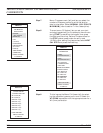
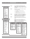
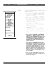
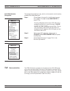

Step 12. When menu C18B (left) appears, make the following
selections (for 3-line):
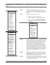
a.
Move the cursor to DEVICE 1 LINE 1 (REF)
and key in the value (typically 1.00 cm). Press
the Enter key to select.
b.
Move the cursor to DEVICE 2 LINE/MATCH.
Both here, and for the next choice, you have an
-
other decision to make: whether your calibration
is to be LRL or LRM. For this selection, the En
-
ter key acts as a toggle.
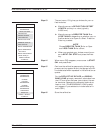
c.
If you toggle such that LINE turns red, then
key in the value for line 2. This value depends
on your frequency range.
d.
If you toggle MATCH red, observe that
LOWBAND appears. This indicates that your
reflection device is a low-band load. This load
must have a passband such that it passes all
frequencies from the start to the breakpoint (see
below).
e.
Move the cursor to DEVICE 3 LINE/MATCH.
If device 3 is a line, key in the value. If it is a
match, the term HIGHBAND will appear. This
indicates that your match is a high-band load.
This load must have a passband such that it
passes all frequencies from the breakpoint to
the stop frequency.
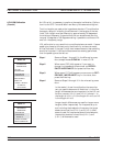
f.
Move the cursor to BREAKPOINT and enter
your breakpoint frequency. For two-line LRL cal
-
ibrations, select a breakpoint equal to the upper
frequency of the low frequency LRL line. For a
combined LRL and LRM calibration, select a
breakpoint equal to the top frequency of the cali
-
bration divided by six; for instance, to cover the
frequency range 0.04 to 60 GHz, select 10 GHz
as the breakpoint.
g. When you have made all selections, move the
cursor to NEXT CAL STEP and press Enter to
produce the next menu.
LRL/LRM CALIBRATION MEASUREMENT CALIBRATION
7-42 37xxxE OM
MENU C18B
CHANGE LRL/LRM
PARAMETERS
NEXT CAL STEP
CHARACTERIZE
CAL DEVICES
DEVICE 1
LINE 1 (REF)
XX.XXXX
DEVICE 2
LINE/MATCH
XX.XXXX/LOWBAND
DEVICE 3
LINE/MATCH
XX.XXXX/HIGHBAND
FREQ AFTER
WHICH THE USE
OF DEVICE 2
AND DEVICE 3
IS EXCHANGED
BREAKPOINT
XXX.XXXXXXXXXGHZ
PRESS <ENTER>
TO SELECT
OR SWITCH