


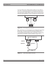

This approach offers two advantages:
q
It minimizes wear on the more expensive test set and cable con
-
nectors
q
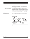
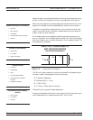
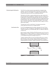
It provides a simple solution to measuring non-insertable devices
(e.g., a filter with K female input and output connectors) by
merely swapping PEAs after calibration. See Figure 7-4
NOTE
In this and other discussions, we will talk about
“insertable” and “non-insertable” devices. Insertable de
-
vices have an insertable connector pair (i.e., male input
and female output connectors) and can be measured after
a through calibration. A non-insertable device has a
non-insertable pair of connectors. This would be the case if
it included female connectors on both ports or different
connector types on each port. Therefore, “non-insertables”
cannot be connected directly into the measurement path
without an adapter.
Understanding the
Calibration System
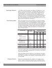
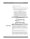
Measurement errors must be reduced by a process that uses calibra
-
tion standards. The standards most commonly used are Opens, Shorts,
and Z
0
(Characteristic Impedance) Loads. In conjunction with a
through connection, these standards can correct for the major errors in
a microwave test system. These errors are Directivity, Source Match,
Load Match, Isolation, and Frequency Tracking (reflection and trans
-
mission).
Calibration also corrects for many internal system errors, such as RF
leakage, IF leakage, and system component interaction.
Random errors such as noise, temperature, connector repeatability,
DUT sensitive leakages, frequency repeatability, and calibration vari
-
ables are not completely correctable. However, some of them can be
minimized by careful control. For instance: temperature effects can be
reduced by room temperature control, calibration variables can be re
-
37xxxE OM 7-5
MEASUREMENT CALIBRATION DISCUSSION
Calibration
Measurement
MF
PEA
USING THE PHASE-EQUAL INSERTABLE
(PEI)
F
MF
MFMF MFMF
DUT
TEST
PORT
TEST
PORT
TEST
PORT
TEST
PORT
PEA
PEA
PEA
M
Figure 7-4. Using Phase-Equal Insertables