


duced through improved technique and training, and frequency errors
can be virtually eliminated by the fully synthesized internal source.
We know that adapters and cables degrade the basic directivity of the
system, but these errors are compensated by vector error correction.
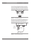
In general, transmission measurement errors are source match, load
match, and tracking; while reflection measurement errors are source
match, directivity, and tracking.
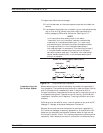
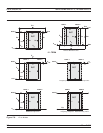
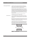
Error modeling and flow graphs are techniques used to analyze the
errors in a system. Error models describe the errors, while flow graphs
show how these errors influence the system. Error models (Figure 7-5)
can become quite complex.
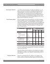
The 37xxxE offers a selection of calibration possibilities depending on
the user’s needs. These possibilities are as follows:
q
Frequency Response
q
Reflection Only—1 Port
q
1 Path, 2 Port
q
12-Term—2 Port, Both Directions
These calibration types are described below.
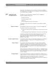
Frequency Response: Corrects for one or both of the transmission error
terms associated with measurements of S21, S12, or both.
DISCUSSION MEASUREMENT CALIBRATION
7-6 37xxxE OM
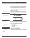
INTERNAL SYSTEM ERRORS
·
RF Leakage
·
IF Leakage
·
System Interaction
RANDOM ERRORS
·
Frequency
·
Repeatability
·
Noise
·
Connector Repeatability
·
Temperature/Environmental
Changes
·
Calibration Variables
ERRORS REDUCED BY CALIBRATION
·
Directivity
·
Source Match
·
Load Match
·
Frequency Sensitivity (Tracking)
·
Isolation
DIRECTIVITY, SOURCE MATCH,
AND TRACKING ERRORS
DISTORTED MEASUREMENT
S
11M
E
D
S
11A
E
S
Figure 7-5. Example of Error Modeling
TRANSMISSION MEASUREMENT
ERRORS
·
Source Match
·
Load Match
·
Tracking