8-7 ADAPTER REMOVAL Using adapters in VNA measurement applications can introduce com
-
plex errors that add to measurement uncertainty. The VNA Adapter
Removal procedure provides for adapter compensation. This on-screen,
menu-driven procedure allows the use of a through-line device or
adapter with different connector types (non-insertables) on either end
to be used for measurement calibration. The electrical effects are sub
-
sequently compensated for. The Adapter Removal procedure is de
-
scribed below.
NOTE
For purposes of explanation, assume that the adapter to be
used is a length of rigid coax with a type N male connector
on one end and an SMA male connector on the other end.
Further assume that the Test Port 1 connector is a type N
female and that the Test Port 2 connector is an SMA fe
-
male (below).
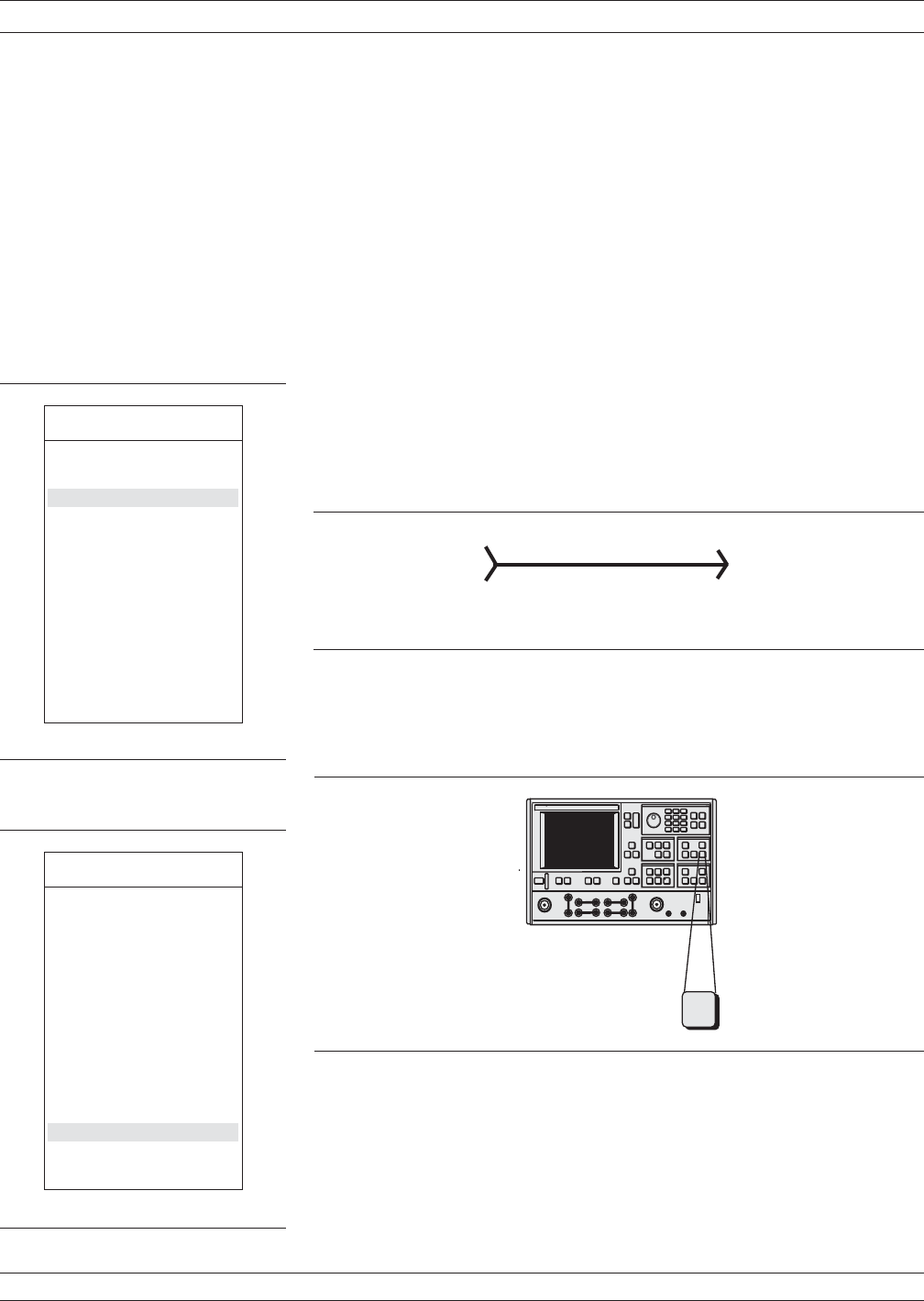
Procedure:
Step 1. Press the Appl key (below) to display the APPLICA-
TIONS menu (top left).
Step 2.
Move the cursor to ADAPTER REMOVAL and
press the Enter key.
Step 3.
Select HELP in the next menu (bottom left) to pro
-
duce the step-by-step procedure shown in
Figure 8-29 (next page).
ADAPTER REMOVAL MEASUREMENTS
8-34 37xxxE OM
Test Adapter
Type N Male
(X’)
SMA Male
(Y’)
Electrical Length: 170 ps
MENU APPL
APPLICATIONS
ADAPTER REMOVAL
SWEPT FREQUENCY
GAIN COMPRESSION
SWEPT POWER
GAIN COMPRESSION
E/O MEASUREMENT
O/E MEASUREMENT
MERGE CAL FILES
PRESS <ENTER>
TO SELECT
MENU CAR1
ADAPTER REMOVAL
12-TERM CALS FOR
X AND Y
MUST EXIST IN THE
CURRENT DIREC
-
TORY
ELECTRICAL LENGTH
OF THE ADAPTER
+XXX.XXXXX ps
REMOVE ADAPTER
HELP
PRESS <ENTER>
TO SELECT
.
-
Measurement
Enhancement
Channels
Display
Appl


