


37xxxE OM B-7
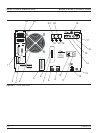
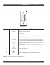
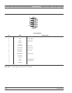
REAR PANEL CONNECTORS CONNECTOR PINOUT DIAGRAMS
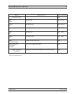
PIN NAME DESCRIPTION
1 STROBE
Printer Strobe. Alow-true pulse thattells the printer validdata has beenplaced onthe
bus.
2-9 DATA 1 thru DATA 8 Data Lines. Bits are HIGH when thedata is logical 1 and LOW whenthe data is alog-
ical 0.
10 ACK NLG
Printer Acknowledgment. A low-true (it varies from printer to printer) pulse sent back
by the printer to acknowledge that the data has been accepted and the printer is
ready to accept more data.
11 BUSY Printer Busy. High-true level sent bythe printer to indicatethat it is not available.This
line is HIGH at the following times: (1) Duringdata entry. (2) While printing. (3) When
off-line. (4) When a printer-error has been signaled.
12 PE Printer Error. High-true level sent by the printer to indicate that it is out of paper.
13 SLCT Select. A high-true logic level.
14 AUTO FEED XT
Automatic Paper Feed. A low-true level that tells the printer to feed the paper
automatically.
15 ERR
Printer Error. A low-true signal that indicates the printer is (1) out of paper,
(2) off-line, or (3) in an error state.
16 INIT
Printer Initial State. A low-true pulse that tells the printer to assume its initial state
and clear its print buffer.
17 SLCT IN
Printer Select Input. A low-true level that permits the printer to accept data.
18-25 DATA RTN Return lines for DATA 1 thru DATA 8 lines.
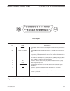
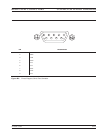
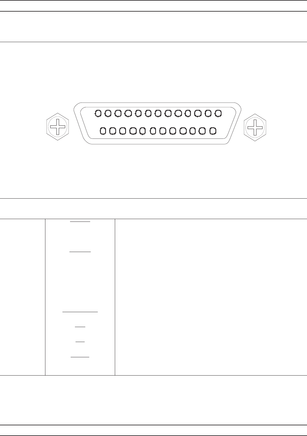
Figure B-3. Pinout Diagram, Printer Connector (1 of 2)
1
13
25
14
Pinout Diagram