


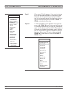
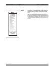
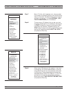
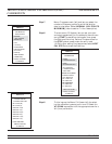

Step 7. Menu C1 (left), which appears next, lets you select
the number of frequency points at which calibration
data is to be taken. Of these choices, which were de
-
scribed in paragraph 7-4, choose NORMAL (1601
POINTS MAXIMUM) for this example.
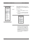
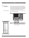
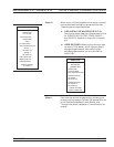
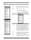
Step 8. The next menu, C2 (below), lets you set your start
and stop frequencies. For this example, move cursor
to START, press 40 on keypad, and press the MHz
terminator key. Perform like operations for the
STOP choice, except make entry read 20 GHz. After
setting the frequencies, select NEXT CAL STEP
and press the Enter key.
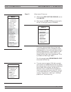
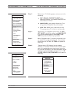
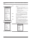
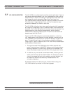
Step 9. When menu C3B (bottom left) appears, if you want
to change any of the parameters shown in blue let
-
ters, place the cursor on that parameter and press
the Enter key. (These choices operate the same as
was described for menu C3 in section 7-4.) For this
example, we change the waveguide parameters.
Move the cursor to WAVEGUIDE PARAMETERS
and press the Enter key.
OFFSET-SHORT CALIBRATION (SSLT) MEASUREMENT CALIBRATION
7-30 37xxxE OM
MENU C1
SELECT
CALIBRATION
DATA POINTS
NORMAL
(1601 POINTS
MAXIMUM)
C.W.
(1 POINT)
N-DISCRETE
FREQUENCIES
(2 TO 1601
POINTS)
TIME DOMAIN
(HARMONIC)
PRESS <ENTER>
TO SELECT
MENU C2
FREQ RANGE OF
CALIBRATION
START
0.0400000000GHz
STOP
20.000000000 GHz
201 DATA PTS
0.099800000 GHz
STEP SIZE
MAXIMUM NUMBER
OF DATA POINTS
1601 MAX PTS
801 MAX PTS
401 MAX PTS
201 MAX PTS
101 MAX PTS
51 MAX PTS
NEXT CAL STEP
PRESS <ENTER>
TO SELECT
MENU C3B
CONFIRM
CALIBRATION
PARAMETERS
WAVEGUIDE
PARAMETERS
INSTALLED
REFLECTION
PAIRING
XXXXXXXX
LOAD TYPE
BROADBAND
THROUGH LINE
PARAMETERS
TEST SIGNALS
START CAL
PRESS <ENTER>
TO SELECT
OR CHANGE