


A-158 37xxxE OM
M ALPHABETICAL LISTING
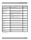
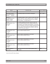
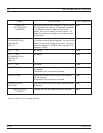
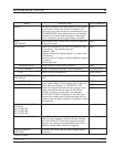
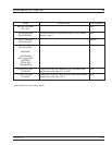
MENU DESCRIPTION GPIB COMMAND
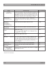
FILTER
PARAMETERS
Provides the readouts for the filter measurement functions, as
well as some selections. When this function is selected, the
graph type for the active channel is automatically set to LOG
MAGNITUDE, and taken out of time domain low pass or band
pass display. Frequency with time gate display is allowed.
None
CENTER FREQ
XX.XXXXXXXXX GHz
Displays the value of Marker 2. Marker 1 displays the
reference value (maximum filter response, or its set value if
delta ref).
FLTC
BANDWIDTH
XXX.XXX dB
D REF MARKER
XX.XXXXXXXXX GHz
Displays the difference between Markers 3 and 4. FLTBW?
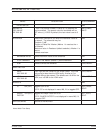
LOSS AT REF
–XXX.XXX dB
Displays the difference between the reference value and 0
dB.
FLTL?
Q
XX.XXX
Displays the Q value.
NOTE: “Q” and “SHAPE FACTOR” are not displayed if they
are toggled OFF in menu M8A.
FLTQ?
SHAPE FACTOR
X.XXX
Displays the Shape Factor value. FLTS?
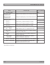
TRACKING ON (OFF) When ON the active marker will change its frequency value
after every sweep to maintain the user entered loss value.
When OFF the marker stays at the same frequency and reads
out the magnitude value at that frequency, except when a
search is triggered.
MKT1; MKT0;
MKTX?
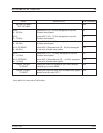
FILTER SETUP Calls menu M8A, which lets you set filter parameters. None
MARKER READOUT
FUNCTIONS
Calls menu M9, which lets you select readout marker
parameters.
None
PRESS <ENTER>
TO SELECT
OR TURN ON/OFF
Pressing the Enter key implements menu selection, or toggles
selected option on or off.
None
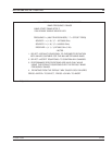
Menu M8, Filter Parameters