Interface
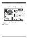
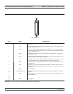
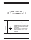
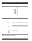
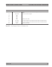
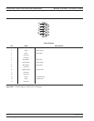
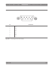
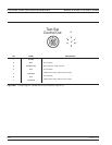
Connectors ...................2-5
Storage ....................4-40
Introduction ...................11-3
K
Keypad ......................4-9
Keys
Calibration ..............4-10 to 4-19
Channel Key-Group .............4-24
Display Key-Group..........4-25 to 4-28
Markers/Limits............4-36 to 4-39
Markers/Limits Key-Group .....4-36 to 4-39
Measurement Key-Group ......4-21 to 4-24
Output Key-Group ..........4-31 to 4-32
Save/Recall Menu ..............4-20
System State .............4-33 to 4-35
System State Key-Group.......4-33 to 4-35
kHz/10E-3/ps/mm Key ..............4-9
L
Limit Frequency Readout Function ......4-36
Limits ......................6-11
Limits Key..................4-5,4-36
Linear Polar Graticule Display Mode ......6-8
Load Match ....................7-6
Log Magnitude Display..............3-9
Log Polar Graticule Display Mode ........6-9
LRL/LRM Calibration Procedure
Coaxial ....................7-44
General ................7-36 to 7-45
Microstrip...................7-37
Waveguide ..................7-46
LRL/LRM Calibration Setup Menu Flow . . . 4-15
M
Marker
Display of ...................6-14
Reference Position ..............6-12
Marker Designation...............6-11
Marker Menu Key..............4-5,4-36
Markers/Limits Key-Group.......4-36 to 4-39
Markers/Limits Keys ............4-5,4-36
Measurement Calibration
Calibration Types ...............7-6
Discussion ...............7-3to7-12
Error Modeling and Flowgraphs .......7-6
Evaluating the Calibration .........7-11
LRL/LRM Procedure .........7-36 to 7-45
Offset-Short Procedure........7-28 to 7-31
Sliding Load, Procedure .......7-13 to 7-18
Standared (SOLT) Procedure ....7-19 to 7-27
Triple Offset-Short Procedure ....7-32 to 7-35
Understanding the Calibration System ...7-5
Measurement Key-Group Description . 4-21 to 4-23
Measurement Keys .............4-8,4-21
Measurement Status ..............6-13
Measurement Uncertainty ............7-3
Measurements
Active Device .............8-24 to 8-28
Adapter Removal...........8-34 to 8-38
Dual Source Control .........8-29 to 8-33
Gain Compression ..........8-39 to 8-57
Group Delay .............8-20 to 8-23
Receiver Mode ............8-58 to 8-61
Time Domain..................9-3
Transmission and Reflection .....8-3to8-11
Menu Flow
Calibration Key-Group Menus . . . 4-10 to 4-19
MARKER MENU Key ............4-36
Save/Recall Key................4-20
Menu Key ..................4-5,4-31
Menu Keys ....................4-9
Menus
Channels Key-Group .............4-24
Display Key-Group..........4-25 to 4-28
Markers/Limits Key-Group
.....4-36 to 4-39
Measurement Key-Group ......4-21 to 4-23
Output Key-Group ..........4-31 to 4-32
System State Key-Group.......4-33 to 4-35
MHz/X1/ns/cm Key ................4-9
Microwave Load .................7-13
Multiple Source Control
Control Formula ...............8-29
Operation ...................8-31
N
Network Analyzers ...............7-13
Basics......................3-6
Description ...................1-3
Error Correction ...............3-11
Measurements .................3-9
Options .....................1-4
SUBJECT INDEX K TO N
37xxxE OM Index-3


