


2-7 EXTERNAL MONITOR
CONNECTOR
The rear panel External Monitor connector allows the internal display
information of the 37xxxE to be connected to an external VGA monitor
(either color or monochrome). The pinout of this 15-pin Type D
connector is shown in Figure B-5, located in Appendix B.
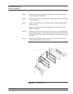
2-8 RACK MOUNT To install the Option 1 Rack Mount rails, refer to the below-listed pro-
cedure.
Step 1. Disconnect the line cord and any other attachments from the instru-
ment.
Step 2. Carefully place the instrument on its top (bottom-side up) on a secure
and stable work surface.
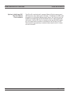
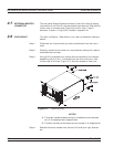
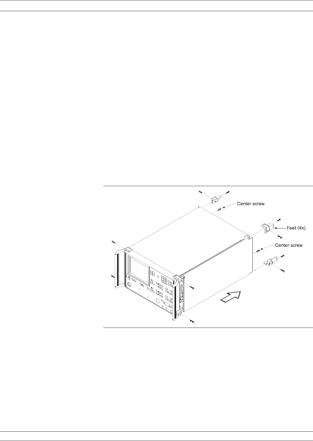
Step 3. Using a Phillips screwdriver, remove the two handles or four bumper
assemblies (and tilt bail, if installed) from the front of the unit, and
the four feet at the rear (Figure 2-1). Save the screws for later use.
NOTES
q The green-headed screws are metric threads and must be used
only in the appropriately tapped holes
q The feet, handles, and bumpers are not reused in this application
Step 4. Remove the center screws from the rear of the left and right side cov
-
ers.
EXTERNAL MONITOR CONNECTOR INSTALLATION
2-8 37xxxE OM
Figure 2-1. Removing Cover