Finally, you can enhance the measurement data by reducing the IF
bandwidth and using averaging and/or smoothing.
q
Change the IF bandwidth by selecting the Video IF BW key
q
Set the averaging and smoothing values by selecting the
Avg/Smooth Menu key
q
Turn on the averaging and smoothing using the Trace Smooth
and Average keys, which have LED’s to let you know that the en
-
hancement is being applied
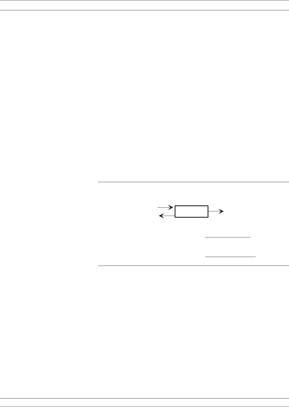
Measurement Discussion
Before going any further, let us take a few moments to review some ba
-
sic principles of network measurements. First, we apply incident en
-
ergy to the input of a test device. If the device’s input impedance dif
-
fers from the measurement system’s impedance, some of that energy is
reflected. The remainder is transmitted through the device. We call the
ratio of reflected-to-incident energy the reflection coefficient. The ratio
of transmitted-to-incident energy we call the transmission coefficient
(Figure 8-3).
These ratios are complex quantities that have magnitude and phase
components. Using vector representation, the vector magnitude is the
ratio of reflected-to-incident magnitude (or transmitted-to-incident
magnitude), while the vector phase is the difference in phase between
the incident energy and the reflected/transmitted energy (Figure 8-4).
37xxxE OM 8-7
MEASUREMENTS TRANSMISSION AND REFLECTION
I N C I D E N T
E N E R G Y
R E F L E C T E D
E N E R G Y
T R A N S M I T T E D
E N E R G Y
R E F L E C T I O N C O E F F I C I E N T =
T R A N S M I S S I O N C O E F F I C I E N T =
R E F L E C T
E D E N E R G Y
I N C I D E N T E N E R G Y
T R A N S M I T T E D E N E R G Y
I N C I D E N T E N E R G Y
B A S I C M E A S U R E M E N T P R I N C I P L E S
D U T
Figure 8-3. Basic Measurement Principles


