


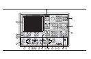

Index 17. Display Keys: (Refer to section 4-7, page 4-25, for
details and menu flow diagrams.)
Graph Type: Displays the two menus that let you
choose the graph type for the active channel.
Set Scale: Displays the appropriate scaling menu,
based on the graph type for the active channel.
Auto Scale: Automatically scales the active chan
-
nel for optimum viewing.
S Params: Displays Menu SP (Appendix A), which
lets you choose between S11, S12, S21, or S22. You
may display the same parameter on two or more
channels.
Ref Plane: Displays the first of two menus that let
you set the reference plane for the active channel in
time or distance. For a correct distance readout, you
must set the dielectric constant to the correct value.
Refer to the discussion in menu RD2 (Appendix A).
Trace Memory: Displays the menus that let you do
any of the following. (1) Store the measured data in
memory. (2) View the stored data. (3) Add, subtract,
multiply, or divide the measured data from the
stored data (normalize to the stored memory). (4)
View both the measured and the stored data simul-
taneously on the active channel. (5) Store/Recall
saved data to disk. Four memories exist—one for
each channel. This lets you normalize the data in
each channel independently. The LED on this but
-
ton lights when the active channel is displaying
memory data or measurement data normalized to
memory.
Index 18. Bias Input Connectors:
Port 1: Provides for supplying a bias voltage for the
Port 1 input.
Port 2: Provides for supplying a bias voltage for the
Port 2 input.
KEY-GROUPS FRONT PANEL OPERATION
4-6 37xxxE OM