


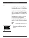
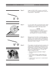
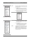
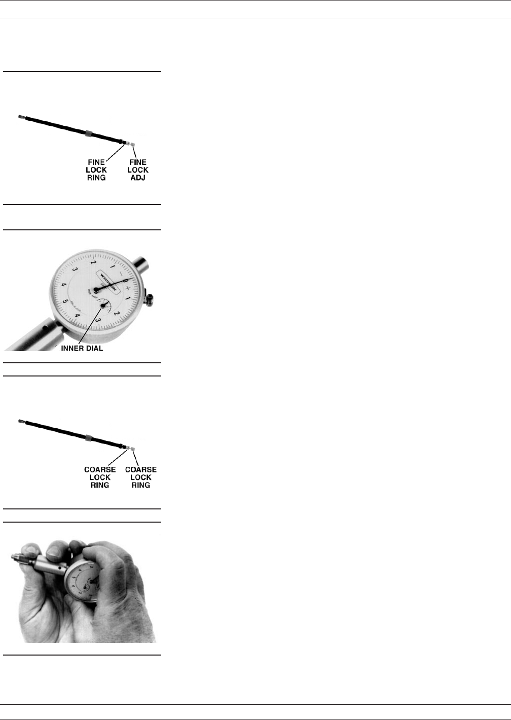
Step 13. Loosen the FINE LOCK ring and turn the FINE
ADJ ring to position the gauge pointer 2-3 small di
-
visions on the “–” side of zero.
Step 14. Turn the FINE LOCK ring clockwise to both tighten
the adjustment and place the pointer exactly to “0.”
The Sliding Termination is now ready to use.
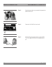
NOTES
Ensure that the inner dial reads “0.”
The following step is not normally necessary.
It needs to be done only if the adjustment
has changed since it was set at the factory.
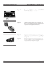
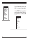
Step 15. With the 01-211 Flush Short installed, loosen the
COARSE LOCK and gently push the COARSE SET
adjustment rod in as far as it will go. This coarsely
sets the center conductor to be flush against the at
-
tached short. Return to Step 2.
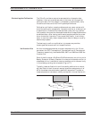
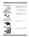
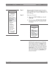
Step 16. The procedure for adjusting the male-connector slid
-
ing termination is essentially the same as that de
-
scribed above. The only difference is that you must
install the female adapter on the end of the gauge
shaft, over the center conductor. To install this
adapter, proceed as follows:
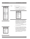
Zero-set the gauge as described in Steps 2
through 5.
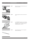
Push the outer locking ring back toward the
gauge and turn it clockwise onto the exposed
threads.
Loosen the lock ring one turn in a counterclock
-
wise direction.
37xxxE OM 7-17
MEASUREMENT CALIBRATION SLIDING TERMINATION