


Data File.....................4-40
Data Plotting ..................4-31
Data Points Key ...............4-8,4-21
Default Parameters .............8-3,8-10
Default Program Key ............4-4,4-33
Default Settings .................4-34
Device ID Key ..................4-21
Display Key-Group ...........4-25 to 4-28
Display Keys.................4-6,4-25
Domain Key .................4-8,4-21
Drive, External SCSI ...............2-4
Dual Channel Display Mode ...........6-4
Dual Channel Rectilinear Display Mode ....6-8
Dual Source Control
Pre-operational Setup ............8-30
Dual Source Control Measurements
Discussion ..............8-29 to 8-33
Dual Trace Overlay Display Mode ........6-6
E
E/O Measurements ...............8-65
Equipment Setup...............8-65
Measurement Procedure ...........8-66
Enhancement Keys .............4-7,4-29
Enter Key .....................4-9
Error Messages ..................5-3
Error Modeling and Flowgraphs .........7-6
Error Terms
Description ..................3-11
Evaluating the Calibration ...........7-11
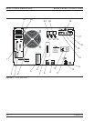
External Monitor Connector ...........2-7
F
Four Channel Display Mode ...........6-5
Fourier Transform ................9-3
Frequency
Range .....................6-12
Frequency Domain ...........9-3,9-8,9-12
Front Panel
Calibration Key-Group Description . 4-10 to 4-19
Channels Key-Group Description ......4-24
Display Key-Group Description . . . 4-25 to 4-28
Key-Group Descriptions ........4-3to4-9
Markers/Limits Key-Group Description . 4-36 to
4-39
Measurement Key-Group Description4-21 to 4-23
Output Key-Group Description . . . 4-31 to 4-32
Save/Recall Key, Description ........4-20
System State Key-Group Description 4-33 to 4-35
G
Gain Compression
Swep Power Gain Compression Measurement
........................8-43
Swept Frequency Measurement .......8-51
Gain Compression Measurements
Discussion ..............8-39 to 8-57
Gating ......................9-12
General Description ............3-3to3-4
GHz/10E+3/Ms/m Key ..............4-9
GPIB
Indicators ...................4-3
GPIB Addresses .................2-6
GPIB Interface to External Plotter .......2-6
GPIB Setup and Interconnection ........2-5
Graph Data Types ................6-7
Graph Type Key...............4-6,4-25
Group Delay
Applications..................8-23
Discussion ..................8-20
Equation ...................8-21
Frequency Aperture .............8-21
Group Delay Measurements ......8-20 to 8-23
H
Hard Copy
Plotter Output ................6-15
Screen-Image Printout ............6-15
Tabular Printout ...............6-15
Hard Copy and Disk Output ..........6-15
Hard Copy Keys ...............4-5,4-31
High Level Noise Test
Test Procedure ................11-7
High Level Noises Test .............11-6
Hold Key...................4-8,4-21
I
Identification Number ..............1-3
Impulse Response.................9-4
Initial Inspection .................2-3
Initial Setup ...................11-3
Insertables ....................7-5
Index-2 37xxxE OM
E TO I SUBJECT INDEX