LRL/LRM Calibration
(Waveguide)
The waveguide procedure is very similar to the coaxial and microstrip
procedures already described.
Step 1. Follow Steps 1 through 6 in the Microstrip proce
-
dure, page 7-37, except choose WAVEGUIDE in
menu C11A.
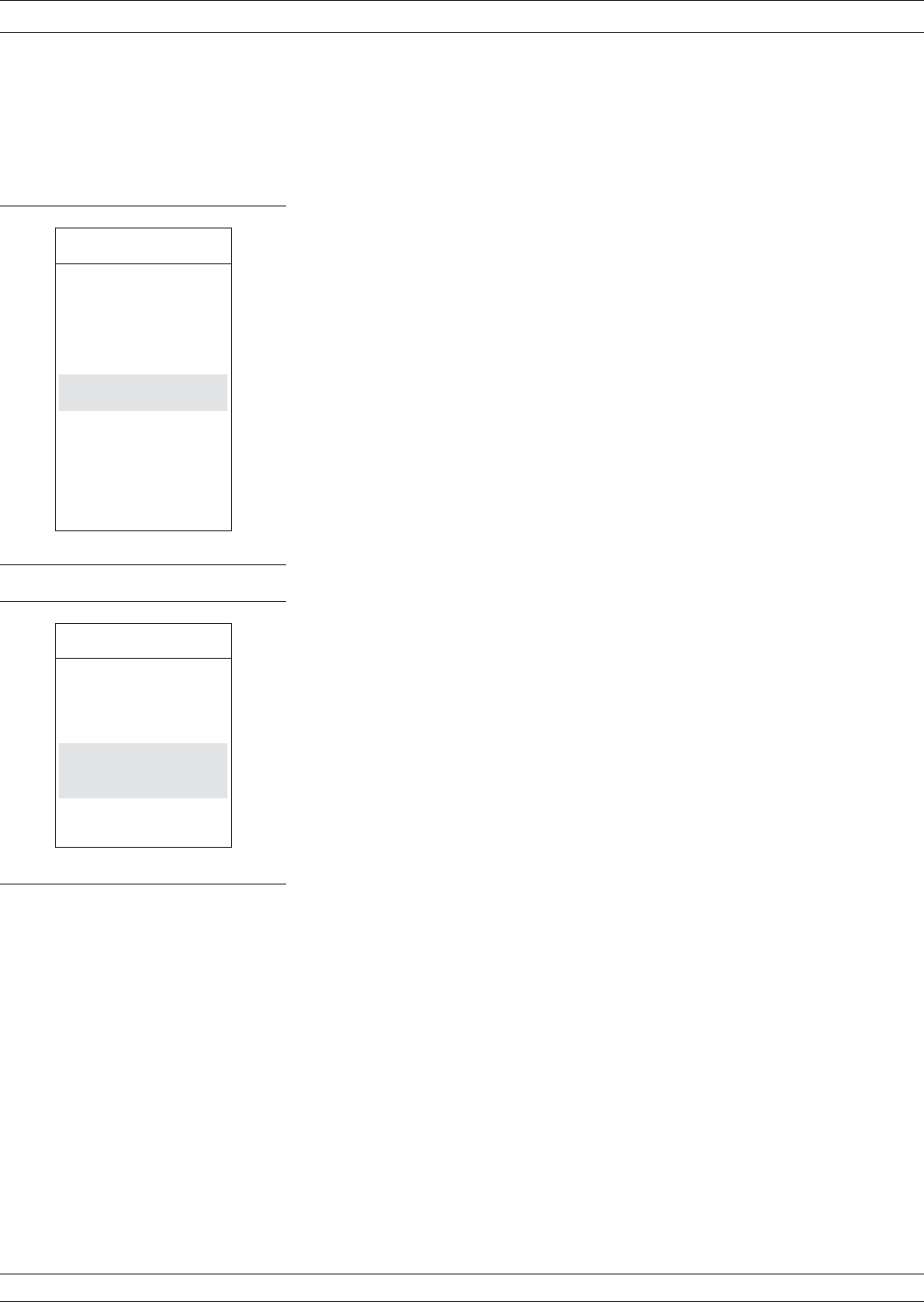
The only difference is with menu C3F (left). For a
waveguide calibration, move the cursor to WAVE
-
GUIDE CUTOFF FREQ and press Enter. This ac
-
tion calls menu C15B, which lets you enter the
waveguide cutoff frequency. After doing so, you are
returned to menu C3F.
Step 2. When menu C3F reappears, place cursor on
CHANGE LRL/LRM PARAMETERS and press
the Enter key.
Step 3. Follow Steps 9 through 13, page 7-40, in the
Microstrip procedure.
7-8 TRM CALIBRATION The TRM Calibration procedure is the same as the LRL/LRM proce
-
dure, previous page, except that certain parameters have been set by
default so that the calibration is simpler to perform (e.g., the L-param
-
eter in the LRM calibration has been set to equal a length of 0 mm for
a through, and the R-parameter is set for a short).
TRM CALIBRATION MEASUREMENT CALIBRATION
7-46 37xxxE OM
MENU C3F
CONFIRM
CALIBRATION
PARAMETERS
LRL/LRM
PARAMETERS
WAVEGUIDE
CUTOFF FREQ
TEST SIGNALS
START CAL
PRESS <ENTER>
TO SELECT
OR CHANGE
MENU C15B
ENTER
WAVEGUIDE
CUTOFF
FREQUENCY
WAVEGUIDE
CUTOFF FREQ
XX.XXXX GHz
PRESS <ENTER>
WHEN COMPLETE


