


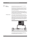
E/O Measurement Procedure
The following procedure will explain ways of using the MN4765A
photo-diode to make an E/O measurement of a modulator DUT. The
same set up can be used for a user characterized photo-diode as well.
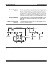
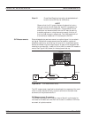
Step 1. Set-up the measurement as shown in Figure 8-33.
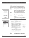
Step 2. Perform a 12-term calibration on the VNA over the
frequency range of interest with reference planes at
the DUT input and the photo-diode output. (Refer to
section 7-4 for the 12-term calibration steps.)
Step 3. Press Save/Recall to save the calibration and set-up
to the SD Card or USB drive.
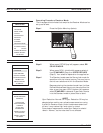
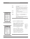
Step 4. Press the Appl key to display the applications menu
(left).
Step 5.
Move the cursor to E/O MEASUREMENT and
press Enter.
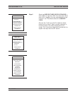
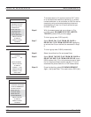
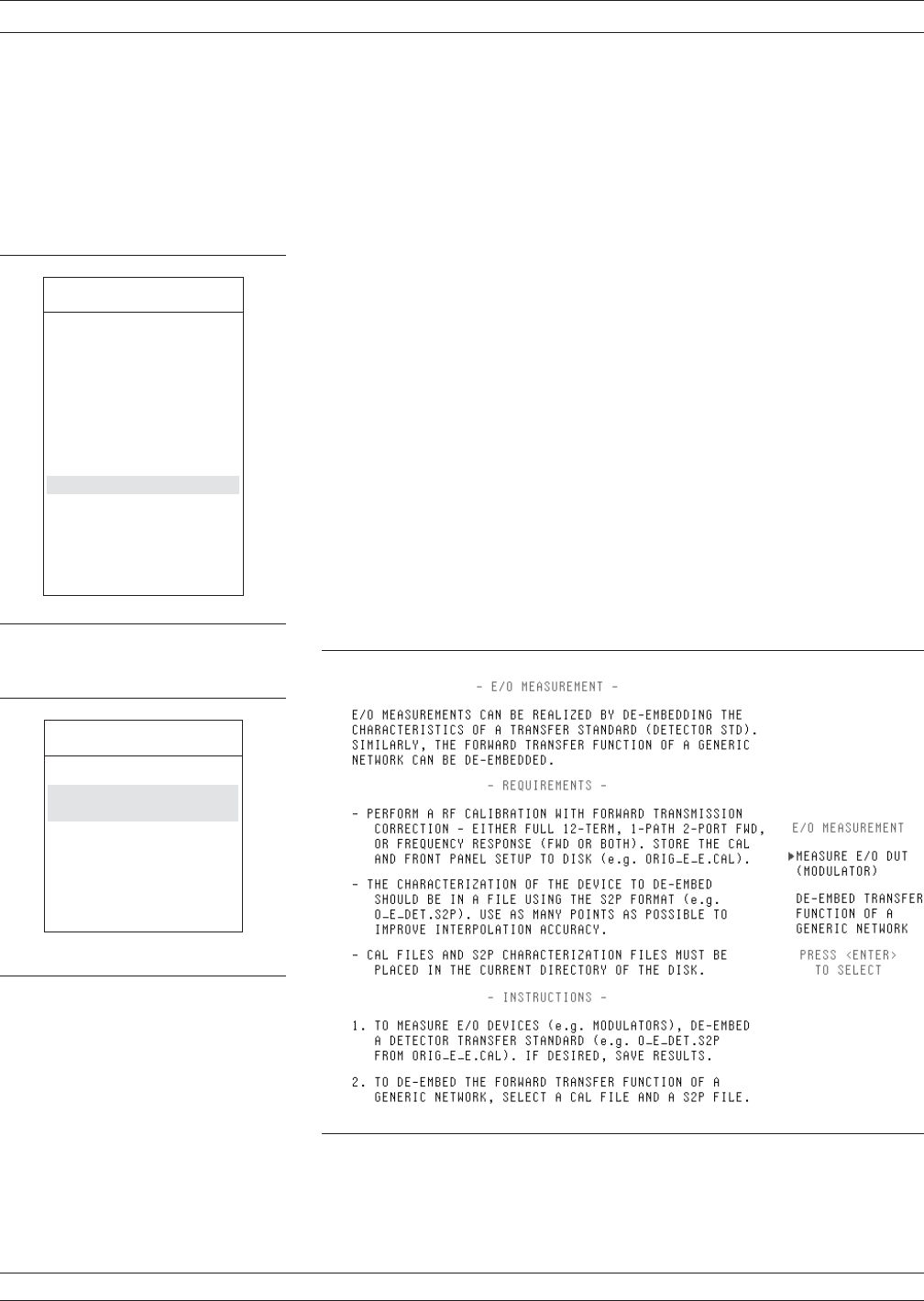
This brings up menu DE1 (left) and the step-by-step
procedure, Figure 8-34, for making the measure-
ment.
Step 6.
Select MEASURE E/O DUT (MODULATOR) and
press Enter.
OPTICAL APPLICATION MEASUREMENTS
8-66 37xxxE OM
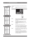
MENU APPL
APPLICATIONS
ADAPTER REMOVAL
SWEPT FREQUENCY
GAIN COMPRESSION
SWEPT POWER
GAIN COMPRESSION
E/O MEASUREMENT
O/E MEASUREMENT
MERGE CAL FILES
PRESS <ENTER>
TO SELECT
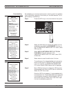
MENU DE1
E/O MEASUREMENT
MEASURE E/O DUT
MODULATOR
DE-EMBED TRANSFER
FUNCTION OF A
GENERIC NETWORK
PRESS <ENTER>
TO SELECT
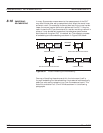
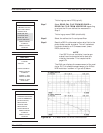
Figure 8-34. E/O Measurement Menu