


37xxxE OM B-5
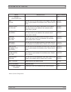
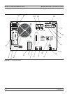
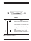
REAR PANEL CONNECTORS CONNECTOR DESCRIPTIONS
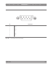
1. Printer Out: 25-pin connector that provides a parallel in
-
terface to the companion printer. Figure B-3 describes the
signal lines and shows the connector pinout.
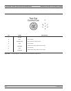
2. Serial: 9-pin connector provides provides control for
AutoCal module. Figure B-5 provides a pinout diagram.
3. VGA OUT: 15-pin connector provides VGA output of
37xxxE video display. Figure B-4 providesa pinout diagram.
4. Fan: Used for instrument cooling.
5. External I/O: Provide I/O access for Channel 1 through 4
limit and Port 1 and 2 bias voltages. Figure B-3 provides a
pinout diagram.
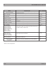
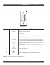
6. Mini-USB Port: Not accessable. For Anritsu service use
only.
7. SD Card Slot: SD Card slot used for replacing the internal
storage device (SD Card).
8. Bias Fuses, Port 1: Fuse, 0.5A, 3AG, 250V, provides pro-
tection for external bias being applied to the active device
connected to test port 1 without disturbing the accuracy of
the 37xxxE measurement.
9. Bias Fuses, Port 2: Fuse, 0.5A, 3AG, 250V, provides pro-
tection for external bias being applied to the active device
connected to test port 2 without disturbing the accuracy of
the 37xxxE measurement.
10. Line Voltage Input: Three-prong ac plug that provides in-
put for the input-line power. The line voltage must be be-
tween 85 and 264 Vac rms, 43 to 63 Hz.
11. Power On/Off: Turns the line power on or off.
12. Ethernet Port: RJ45 jack allows connection to a Local
Area Network (LAN) for remote programming and data ex-
traction.
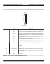
13. External PS2 Keyboard Port: Provides for connecting
any external keyboard with a standard PS2 connector. All
alphanumeric field entries can be input from this keyboard.
These inputs include Device ID, Model, Date, Operator
Identification, frequencies, filenames, as well as com-
ment-type entries. The analog knob and keypad input for
these entries remains active. The F1 through F12 function
keys can beused to access certain key and menufunctions.
A template is provided. Two versions of an actual-size tem-
plate are provided in a foldout page at the end of Chapter 4
in the event a replacement is needed.
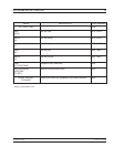
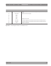
14. (Option 12) a1: IF input from 3738A Broadband Test Set.
SMA connector that should be terminated (on chain) when
not in use.
15. (Option 12) b1: IF input from 3738A Broadband Test Set.
SMA connector that should be terminated (on chain) when
not in use.
16. (Option 12) a2: IF input from 3738A Broadband Test Set.
SMA connector that should be terminated (on chain) when
not in use.
17. (Option 12) b2: IF input from 3738A Broadband Test Set.
SMA connector that should be terminated (on chain) when
not in use.
18. (Option 12) Test Set Control Out: Provides control for
3738ABroadband Test Set. Figure B-6 provides a pinout di-
agram. TTL levels.
19. External Trigger: Allows an external TTL signal to sync
the 37xxxE measurements; 10 kW input impedance, BNC
female.
20. External Anlg Out: Provides up to a ±10V signal for use in
driving an external plotter or antenna (CW draw).
21. Ext Anlg In: Provides input to the A5 A/D Converter PCB.
BNC connector allows an external dc voltage to be mea-
sured by the internal analog-to-digital converter circuit.
22. 10 MHz Ref OUT 0dBm 50W: BNC connector that allows
the internal 10 MHz reference to be used to phase lock an
external counter or other measuring instrument. Level is
typically 0 dBm into 50W impedance.
23. 10 MHz Ref IN 0dBm 50W: BNC connector that allows an
external 10 MHzsignal (–5 to +5dBm) to be used asthe fre-
quency reference for phase locking the source frequency.
50W impedance.
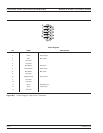
24. Dedicated GPIB: IEEE 488 standard 24-pin connector
that allows the 37xxxE to remotely control a 2nd frequency
source, an external plotter, analyzer, or other peripheral.
Figure B-2 provides a pinout diagram.
25. IEEE 488.2 GPIB: IEEE 488 standard 24-pin connector
that provides for remotely controlling the 37xxxE from an
external computer/controller via the IEEE-488 bus (GPIB).
Figure B-2 provides a pinout diagram.