


Index 4. System State Keys: (Refer to section 4-10,
page 4-33, for details and menu flow diagrams.)
Default Program: Resets the front panel to the fac
-
tory-preset state and displays Menu SU1 or SU3
(Appendix A). Pressing this key in conjunction with
the “0” or “1” key resets certain internal memories
and front panel key states (refer to sections 4-5 and
4-10).
NOTE
Use of the Default Program key will destroy
front panel and calibration setup data, un
-
less they have been saved to disk.
Utility Menu: Displays the first in a series of menus
that let you perform storage and other utility-type
functions and operations.
Index 5. Port 1 Test Connector: Provides an input test con-
nection for the device-under-test (DUT).
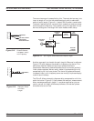
Index 6. Port 1 Source Loop: Provides for inserting addi-
tional amplification on Port 1 before the coupler.
Index 7. Calibration Keys: (Refer to section 4-3, page 4-10,
for details and menu flow diagrams.)
Begin Cal: Calls up the first in a sequence of
menus that guide you through a measurement cali
-
bration. Refer to section 4-3 for a detailed discussion
of the calibration keys, indicators, and menus.
Apply Cal: Turns on and off the applied error cor
-
rection and tune mode.
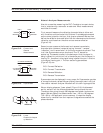
Index 8. a1 Loop: Provides direct access to Reference A
channel on Port 1 over the entire frequency range.
Refer to the front panel for damage levels.
Index 9. a2 Loop: Provides direct access to Reference B
channel on Port 2 over the entire frequency range.
Refer to the front panel for damage levels.
Index 10. b1 Loop: Provides direct access to Test A channel
on Port 1 over the entire frequency range. Refer to
the front panel for damage levels.
Index 11. b2 Loop: Provides direct access to Test B channel
on Port 2 over the entire frequency range. Refer to
the front panel for damage levels.
KEY-GROUPS FRONT PANEL OPERATION
4-4 37xxxE OM