


CHAPTER 13. CONFIGURING INTERNET TELEPHONY SUPPORT 13-9
BETA DOCUMENT - PRELIMINARY & CONFIDENTIAL
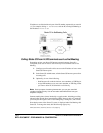
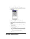
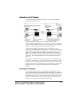
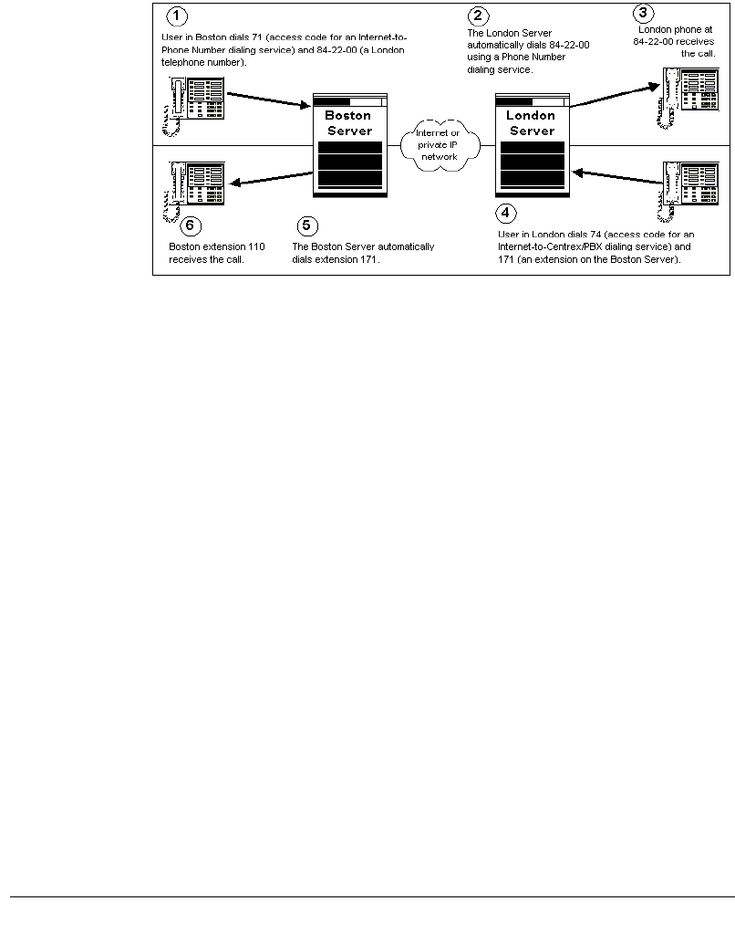
Illustration of an IP Gateway
The following diagram illustrates Strata CS Servers in London and Boston,
connected using an IP Gateway.
In the top example, the administrator at the Boston Server set up an
Internet-to-Phone Number dialing service with an access code of 71. The London
Server has a Phone Number dialing service. Users in Boston can now dial phone
numbers in London by dialing 71 followed by the phone number.
In the bottom example, the administrator at the London Server set up an
Internet-to-Centrex/PBX Extension dialing service—configured to connect to the
Boston Server’s internal dial tone—with an access code of 74. Users in London
can now dial extensions in Boston by dialing 74 followed by the extension.
Note:
You can enable users to dial remote extensions directly, without dialing the
access code. See “Creating Gateway users to unify two Strata CS Servers” on
page 13-17.
To establish the TCP/IP connection, each administrator creates an IP Gateway
that points to the other Server. The administrator can use the IP Gateway on his
local Server to control dialing permissions for incoming calls. For example, the
London administrator can prevent Boston users from making long-distance calls
through his Server, by changing the dialing permissions of the Boston IP
Gateway.
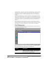
Creating an IP Gateway
To connect two Strata CS Servers over IP Gateways, administrators on each
Server must create an IP Gateway that points to the other Server. For example, on
an IP Gateway connection between Boston and London, the Boston Server has an
IP Gateway called “London,” and the London Server has an IP Gateway called
“Boston.” Each IP Gateway has an extension and password that the other IP
Gateway uses to log in when connecting IP Gateway calls.