


Development System Reference Guide www.xilinx.com 111
PKG File
R
• Number of internal 3-state buffers in a device: NUM_TBUFS PER ROW=#
• If unavailable on a particular device or package, PartGen reports:
NUM_PPC=#
NUM_GT=#
NUM_MONITOR=#
NUM_DPM=#
NUM_PMCD=#
NUM_DSP=#
NUM_FIFO=#
NUM_EMAC=#
NUM_MULT=#
PKG File
The PKG files correlate IOBs with output pin names. The –p option generates a three
column entry describing the pins. The –v option adds six more columns of descriptive pin
information.
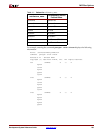
For example, the command partgen –p xc2v40 generates the package files:
2v40cs144.pkg and 2v40fg256.pkg. Following is a portion of the package file for the
2v40cs144:
package 2v40cs144
pin PAD96 D3
pin PAD2 A3
pin PAD3 C4
pin PAD4 B4
.
.
.
The first column contains either pin (user accessible pin) or pkgpin (dedicated pin). The
second column specifies the pin name. For user accessible pins, the name of the pin is the
bonded pad name associated with an IOB on the device, or the name of a multi-purpose
pin. For dedicated pins, the name is either the functional name of the pin, or no connection
(N.C.). The third column specifies the package pin.
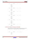
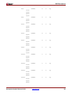
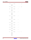
The command partgen –v generates package (.pkg) files and generates a nine column entry
describing the pins. The first three columns are described in the preceding section.
The fourth and fifth columns, IO_BANK, is a positive integer associated with a bank, or –1
for no bank association. The sixth column, specifying function name, consists of a string
indicating how the pin is used. If the pin is dedicated, then the string will indicate a specific
function. If the pin is a generic user pin, the string is IO. If the pin is multipurpose, an
underscore-separated set of characters will make up the string. The seventh column
indicates the closest CLB row or column to the pin, and appears in the form R[0-9]C[0-9].
Column eight is comprised of a string for each pin associated with a LVDS IOB. The string
consists of and index and the letter M or S. Index values will go from 0 to the number of
LVDS pairs. The value for a non-LVDS pin will default to N.A. The ninth column is
composed of flight-time data in units of microns. If no flight-time data is available, this
column contains zeros.