


230 www.xilinx.com Development System Reference Guide
Chapter 12: TRACE
R
Setup Times
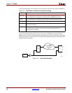
The external setup time is defined as the setup time of DATAPAD within IOB relative to
CLKPAD within CLKIOB. When a guaranteed external setup time exists in the speed files
for a particular DATAPAD and the CLKPAD pair and configuration, this number is used
in timing reports. When no guaranteed external setup time exists in the speed files for a
particular DATAPAD and CLKPAD pair, the external setup time is reported as the
maximum path delay from DATAPAD to the IFD plus the maximum IFD setup time, less
the minimum of maximum path delay(s) from the CLKPAD to the IFD.
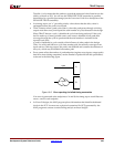
Hold Times
The external hold time is defined as the hold time of DATAPAD within IOB relative to
CLKPAD within CLKIOB. When a guaranteed external hold time exists in the speed files
for a particular DATAPAD and the CLKPAD pair and configuration, this number is used
in timing reports.
When no guaranteed external hold time exists in the speed files for a particular DATAPAD
and CLKPAD pair, the external hold time is reported as the maximum path delay from
CLKPAD to the IFD plus the maximum IFD hold time, less the minimum of maximum
path delay(s) from the DATAPAD to the IFD.
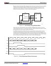
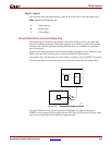
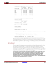
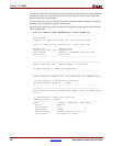
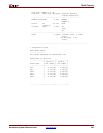
Summary Report
The summary report includes the name of the design file being analyzed, the device speed
and report level, followed by a statistical brief that includes the summary information and
design statistics. The report also list statistics for each constraint in the PCF, including the
number of timing errors for each constraint.
A summary report is produced when you do not enter an –e (error report) or –v (verbose
report) option on the TRACE command line.
Two sample summary reports are shown below. The first sample shows the results
without having a physical constraints file. The second sample shows the results when a
physical constraints file is specified.
If no physical constraints file exists or if there are no timing constraints in the PCF, TRACE
performs default path and net enumeration to provide timing analysis statistics. Default
path enumeration includes all circuit paths to data and clock pins on sequential
components and all data pins on primary outputs. Default net enumeration includes all
nets.