


282 www.xilinx.com Development System Reference Guide
Chapter 15: BSDLAnno
R
Boundary Register Description
The boundary register description gives the structure of the boundary scan cells on the
device. Each pin on a device may have up to three boundary scan cells, with each cell
consisting of a register and a latch. Boundary scan test vectors are loaded into or scanned
from these registers.
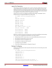
For example (from the xcv50e_pq240.bsd file):
attribute BOUNDARY_REGISTER of XCV50E_PQ240 : entity is
-- cellnum (type, port, function, safe[, ccell, disval, disrslt])
" 0 (BC_1, *, controlr, 1)," &
" 1 (BC_1, IO_P184, output3, X, 0, 1, PULL0)," & -- PAD48
" 2 (BC_1, IO_P184, input, X)," & -- PAD48
Every IOB has three boundary scan registers associated with it: control, output, and input.
BSDLAnno modifies the boundary register description as described in the “BSDL File
Modifications for Single-Ended Pins” and “BSDL File Modifications for Differential Pins”
sections.
BSDL File Modifications for Single-Ended Pins
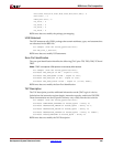
If pin 57 has been configured as a single-ended tri-state output pin, no code
modifications are required:
-- TRISTATE OUTPUT PIN (three state output with an input component)
" 9 (BC_1, *, controlr, 1)," &
" 10 (BC_1, PAD57, output3, X, 9, 1, Z)," &
" 11 (BC_1, PAD57, input, X)," &
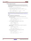
If pin 57 is configured as a single-ended input, modify as follows:
-- PIN CONFIGURED AS AN INPUT
" 9 (BC_1, *, internal, 1)," &
" 10 (BC_1, *, internal, X)," &
" 11 (BC_1, PAD57, input, X)," &
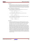
If pin 57 is configured as a single-ended output, it is treated as a single-ended
bidirectional pin:
-- PIN CONFIGURED AS AN OUTPUT
" 9 (BC_1, *, controlr, 1)," &
" 10 (BC_1, PAD57, output3, X, 9, 1, Z)," &
" 11 (BC_1, PAD57, input, X)," &
If pin 57 is unconfigured or not used in the design, do not modify:
-- PIN CONFIGURED AS "UNUSED"
" 9 (BC_1, *, controlr, 1)," &
" 10 (BC_1, PAD57, output3, X, 9, 1, PULL0)," &
" 11 (BC_1, PAD57, input, X)," &