


Development System Reference Guide www.xilinx.com 39
Design Implementation
R
Mapping (FPGAs Only)
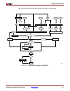
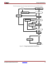
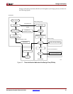
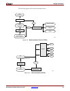
For FPGAs, the MAP command line program maps a logical design to a Xilinx FPGA. The
input to MAP is an NGD file, which contains a logical description of the design in terms of
both the hierarchical components used to develop the design and the lower-level Xilinx
primitives, and any number of NMC (hard placed-and-routed macro) files, each of which
contains the definition of a physical macro. MAP then maps the logic to the components
(logic cells, I/O cells, and other components) in the target Xilinx FPGA.
The output design from MAP is an NCD file, which is a physical representation of the
design mapped to the components in the Xilinx FPGA. The NCD file can then be placed
and routed, using the PAR command line program. See Chapter 7, “MAP” for detailed
information.
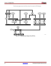
Placing and Routing (FPGAs Only)
For FPGAs, the PAR command line program takes a mapped NCD file as input, places and
routes the design, and outputs a placed and routed NCD file, which is used by the
bitstream generator, BitGen. The output NCD file can also act as a guide file when you
reiterate placement and routing for a design to which minor changes have been made after
the previous iteration. See Chapter 9, “PAR” for detailed information.
You can also use the FPGA Editor GUI tool to do the following:
• Place and route critical components before running automatic place and route tools
on an entire design
• Modify placement and routing manually; the editor allows both automatic and
manual component placement and routing
Note:
For more information, see the online Help provided with the FPGA Editor.
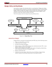
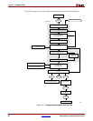
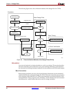
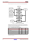
Bitstream Generation (FPGAs Only)
For FPGAs, the BitGen command line program produces a bitstream for Xilinx device
configuration. BitGen takes a fully routed NCD file as its input and produces a
configuration bitstream—a binary file with a .bit extension. The BIT file contains all of the
configuration information from the NCD file defining the internal logic and
interconnections of the FPGA, plus device-specific information from other files associated
with the target device. See Chapter 14, “BitGen” for detailed information.
After you generate your BIT file, you can download it to a device using the iMPACT GUI.
You can also format the BIT file into a PROM file using the PromGen command line
program and then download it to a device using the iMPACT GUI. See Chapter 16,
“PROMGen” of this guide or the iMPACT online help for more information.