


212 www.xilinx.com Development System Reference Guide
Chapter 12: TRACE
R
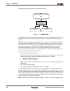
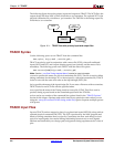
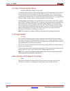
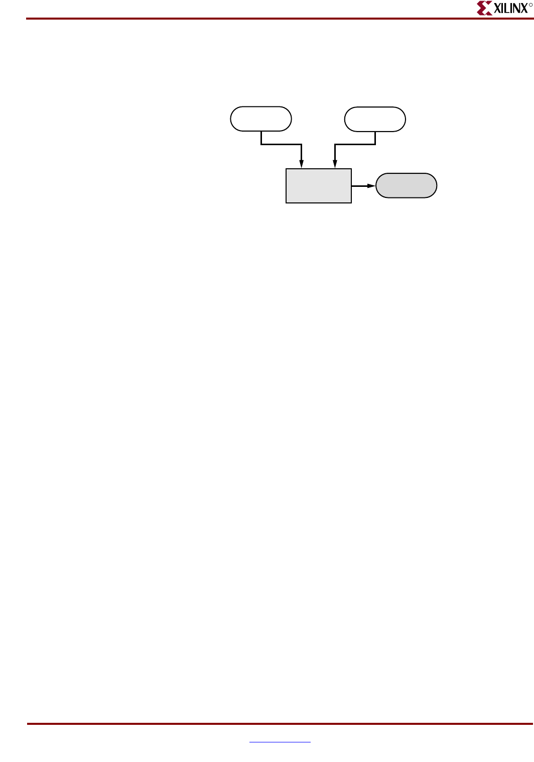
The following figure shows the primary inputs and outputs to TRACE. The NCD file is the
output design file from MAP or PAR, which has a .ncd extension. The optional PCF is the
physical constraints file, which has a .pcf extension. The TWR file is the timing report file,
which has a .twr extension.
TRACE Syntax
Use the following syntax to run TRACE from the command line:
trce
[options] design[.ncd] [constraint[.pcf]]
TRACE can also be used in conjunction with a macro file (XTM), where all traditional
inputs (NCD and PCF) and outputs (timing reports) are optional, and the macro file is
mandatory. The following syntax runs TRACE with the macro file option:
trce –run macro[.xtm] design
[.ncd] [constraint[.pcf]
Note: See the “–run (Run Timing Analyzer Macro)” section for more information.
constraint specifies the name of a physical constraints file (PCF). This file is used to define
timing constraints for the design. If you do not specify a physical constraints file, TRACE
looks for one with the same root name as the input design (NCD) file.
design specifies the name of the input design file. If you enter a file name with no extension,
TRACE looks for an NCD file with the specified name.
macro specifies the name of the Timing Analyzer macro file (XTM). This file is used to
produce timing reports based on the commands specified in the XTM file.
options can be any number of the command line options listed in the “TRACE Options”
section of this chapter. Options need not be listed in any particular order unless you are
using the –stamp (Generates STAMP timing model files) option. Separate multiple options
with spaces.
TRACE Input Files
Input to TRACE can be a mapped, a placed, or a placed and routed NCD file, along with an
optional physical constraints file (PCF). The PCF is produced by the MAP program and
based on timing constraints that you specify. Constraints can show such things as clock
speed for input signals, the external timing relationship between two or more signals,
absolute maximum delay on a design path, and general timing requirements for a class of
pins.
Figure 12-1: TRACE flow with primary input and output files
NCD
TRACE
PCF
(optional)
TWR
X7218