36 www.xilinx.com Development System Reference Guide
Chapter 2: Design Flow
R
Block Placement
Block placement can be constrained to a specific location, to one of multiple locations, or to
a location range. Locations can be specified in the schematic, with synthesis tools, or in the
User Constraints File (UCF). Poor block placement can adversely affect both the placement
and the routing of a design. Only I/O blocks require placement to meet external pin
requirements.
Timing Specifications
You can specify timing requirements for paths in your design. PAR uses these timing
specifications to achieve optimum performance when placing and routing your design.
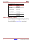
Netlist Translation Programs
Two netlist translation programs allow you to read netlists into the Xilinx software tools.
EDIF2NGD allows you to read an Electronic Data Interchange Format (EDIF) 2 0 0 file. The
NGDBuild program automatically invokes these programs as needed to convert your
EDIF file to an NGD file, the required format for the Xilinx software tools. NGC files
output from the Xilinx XST synthesis tool are read in by NGDBuild directly.
You can find detailed descriptions of the EDIF2NGD, and NGDBuild programs in Chapter
6, “NGDBuild” and “Appendix B”.
Design Implementation
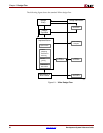
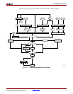
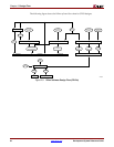
Design Implementation begins with the mapping or fitting of a logical design file to a
specific device and is complete when the physical design is successfully routed and a
bitstream is generated. You can alter constraints during implementation just as you did
during the Design Entry step. See “Constraints” for information.


