


Development System Reference Guide www.xilinx.com 213
TRACE Output Files
R
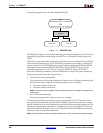
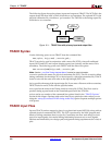
Input files to TRACE:
• NCD file—A mapped, a placed, or a placed and routed design. The type of timing
information TRACE provides depends on whether the design is unplaced (after
MAP), placed only, or placed and routed.
• PCF—An optional, user-modifiable, physical constraints file produced by MAP. The
PCF contains timing constraints used when TRACE performs a static timing analysis.
• XTM file—A macro file, produced by Timing Analyzer, that contains a series of
commands for generating custom timing reports with TRACE. See the Timing
Analyzer online help for information on creating XTM files.
Note:
The Innoveda CAE tools create a file with a .pcf extension when they generate an
Innoveda schematic. This PCF is not related to a Xilinx PCF. Because TRACE automatically
reads a PCF with the same root name as your design file, make sure your directory does not
contain an Innoveda PCF with the same root name as your NCD file.
TRACE Output Files
TRACE outputs the following timing reports based on options specified on the command
line:
TWR—default timing report. The –e (error report) and –v (verbose report) options can be
used to specify the type of timing report you want to produce: summary report (default),
error report, or verbose report.
TWX—XML timing report output by using the –xml option. This report is viewable with
the Timing Analyzer GUI tool. The –e (error report) and –v (verbose report) options apply
to the TWX file as well as the TWR file. See the “–xml (XML Output File Name)” section for
details.
LOG—log file created when the –run option is used. This .log file has the same root name
as the input macro.xtm file.
TRACE generates an optional STAMP timing model with the
–stamp option.
See the “–stamp (Generates STAMP timing model files)” section in this chapter for details.
Note:
For more information on the types of timing reports that TRACE generates, see the “TRACE
Reports” section in this chapter.