


Development System Reference Guide www.xilinx.com 141
MAP Process
R
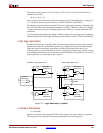
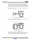
• The aggressive setting transforms the entire bus.
♦ Buses A, B have the same result as the on setting.
♦ Bus C is implemented entirely by CY chain. (30 ≤ the default upper limit for carry
chain transformation)
• The limit setting is the most conservative. It transforms only that portion of the
number of CLB(s) or BUFT(s) per row in a device.
Note:
The –tx option is not used for devices that do not have TBUFs, which include Virtex-4,
Spartan-3, and Spartan-3E device families.
–u (Do Not Remove Unused Logic)
By default (without the –u option), MAP eliminates unused components and nets from the
design before mapping. If –u is specified, MAP maps unused components and nets in the
input design and includes them as part of the output design.
The –u option is helpful if you want to run a preliminary mapping on an unfinished
design, possibly to see how many components the mapped design uses. By specifying –u,
you are assured that all of the design’s logic (even logic that is part of incomplete nets) is
mapped.
–xe (Extra Effort Level)
–xe effort_level
The –xe option is available when running timing-driven packing and placement with the
–timing option. The –xe option sets the extra effort level. The effort_level variable can be set
to n (normal) or c (continue). Extra effort c allows you to direct MAP to continue packing.
MAP continues to attempt to improve packing until little or no improvement can be made.
map –ol high –xe n design.ncd output.ncd design.pcf
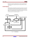
MAP Process
MAP performs the following steps when mapping a design.
1. Selects the target Xilinx device, package, and speed. MAP selects a part in one of the
following ways:
♦ Uses the part specified on the MAP command line.
♦ If a part is not specified on the command line, MAP selects the part specified in
the input NGD file. If the information in the input NGD file does not specify a
complete architecture, device, and package, MAP issues an error message and
stops. If necessary, MAP supplies a default speed.
2. Reads the information in the input design file.
3. Performs a Logical DRC (Design Rule Check) on the input design. If any DRC errors
are detected, the MAP run is aborted. If any DRC warnings are detected, the warnings
are reported, but MAP continues to run. The Logical DRC (also called the NGD DRC)
is described in Chapter 5, “Logical Design Rule Check”.
Note:
Step 3 is skipped if the NGDBuild DRC was successful.