


164 www.xilinx.com Development System Reference Guide
Chapter 9: PAR
R
• Any matching component in the new design is placed in the site corresponding to the
location of the matching guide component, if possible.
• Matching component pins are swapped to match those of the guide component with
regard to matching signals, if possible.
• All of the connections between matching driver and load pins of the matching signals
have the routing information preserved from the guide file with the exception of Vcc
and GND signals.
When PAR runs using a guide design as input, PAR first places and routes any
components and signals that fulfill the matching criteria described above. Then PAR
places and routes the remainder of the logic.
To place and route the remainder of the logic, PAR performs the following:
• If you have selected exact guided PAR (by entering the –gm exact option on the PAR
command line), the placement and routing of the matching logic are locked. Neither
placement nor routing can be changed to accommodate additional logic.
• If you have selected leveraged guided PAR (by entering the –gm leverage option on
the PAR command line), PAR tries to maintain the placement and routing of the
matching logic, but changes placement or routing if it is necessary in order to place
and route to completion and achieve your timing constraints (if possible).
• If you have selected incremental guided PAR (by entering the -gm incremental option
on the PAR command line), your design must have area groups constraints to take
advantage of this option. If an area group has changed, for example, additional or
elimination of logic, this area group will not be guided. The other area groups will
maintain the placement but routing will change to route the design completely and to
achieve your timing constraints (if possible).
Some cases where the leveraged mode is necessary are as follows:
♦ You have added logic that makes it impossible to meet your timing constraints
without changing the placement and routing in the guide design.
♦ You have added logic that demands a certain site or certain routing resource, and
that site or routing resource is already being used in the guide design.
Note:
For Verilog or VHDL netlist designs, re-synthesizing modules typically causes signal and
instance names in the resulting netlist to be significantly different from the netlist obtained in earlier
synthesis runs. This occurs even if the source level Verilog or VHDL code only contains a small
change. Because guided PAR depends on signal and component names, synthesis designs often
have a low
match rate when guided. Therefore, guided PAR is not recommended for most synthesis-
based designs, although there may be cases where it could be a successful alternative technique.
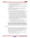
PCI Cores
You can use a guide file to add a PCI Core, which is a standard I/O interface, to your
design. The PCI Core guide file must already be placed and routed. PAR only places and
routes the signals that run from the PCI Core to the input NCD design; it does not place or
route any portion of the PCI Core. You can also use the resulting design (PCI Core
integrated with your initial design) as a guide file. However, you must then use the exact
option for –gm, not leverage, when generating a modified design.
Guided PAR supports precise matching of placement and routing of PCI Cores that are
used as reference designs in a guide file:
• Components locked in the input design are guided by components in the reference
design of a guide file in the corresponding location.