


226 www.xilinx.com Development System Reference Guide
Chapter 12: TRACE
R
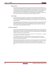
Data Sheet Report
The Data Sheet report summarizes the external timing parameters for your design. Only
inputs, outputs and clocks that have constraints appear in the Data Sheet report for
verbose and error reports. Tables shown in the Data Sheet report depend on the type of
timing paths present in the design, as well as the applied timing constraints.
Unconstrained path analysis can be used with a constraints file to increase the coverage of
the report to include paths not explicitly specified in the constraints file. In he absence of a
physical constraints file (PCF), all I/O timing is analyzed and reported (less the effects of
any default path tracing controls). The Data Sheet report includes the source and
destination PAD names, and either the propagation delay between the source and
destination or the setup and hold requirements for the source relative to the destination.
There are four methods of running TRACE to obtain a complete Data Sheet report:
• Run with advanced analysis (–a)
• Run using default analysis (that is, with no constraints file and without advanced
analysis)
• Construct constraints to cover all paths in the design
• Run using the unconstrained path report for constraints that only partially cover the
design
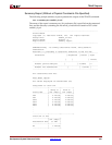
Following are tables, including delay characteristics, that appear in the Data Sheet report:
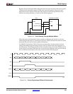
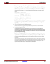
• Input Setup and Hold Times
This table shows the setup and hold time for input signals with respect to an input
clock at a source pad. It does not take into account any phase introduced by the
DCM/DLL. If an input signal goes to two different destinations, the setup and hold
are worst case for that signal. It might be the setup time for one destination and the
hold time for another destination.
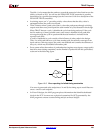
• Output Clock to Out Times
This table shows the clock-to-out signals with respect to an input clock at a source pad.
It does not take into account any phase introduced by the DCM/DLL. If an output
signal is a combinatorial result of different sources that are clocked by the same clock,
the clock-to-out is the worst-case path.
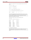
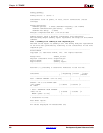
• Clock Table
The clock table shows the relationship between different clocks. The Source Clock
column shows all of the input clocks. The second column shows the delay between the
rising edge of the source clock and the destination clock. The next column is the data
delay between the falling edge of the source and the rising edge of the destination.
If there is one destination flip-flop for each source flip-flop the design is successful. If
a source goes to different flip-flops of unrelated clocks, one flip-flop might get the data
and another flip-flop might miss it because of different data delays.
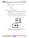
You can quickly navigate to the Data Sheet report by clicking the corresponding item
in the Hierarchical Report Browser.
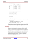
• External Setup and Hold Requirements
Timing accounts for clock phase relationships and DCM phase shifting for all
derivatives of a primary clock input, and report separate data sheet setup and hold
requirements for each primary input. Relative to all derivatives of a primary clock
input covered by a timing constraint.