


248 www.xilinx.com Development System Reference Guide
Chapter 12: TRACE
R
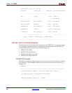
PERIOD Path
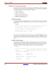
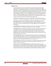
The detail path section shows all of the details for each path in the analyzed timing
constraint. The most important thing it does is identify if the path meets the timing
requirement. This information appears on the first line and is defined as the Slack. If the
slack number is positive, the path meets timing constraint by the slack amount. If the slack
number is negative, the path fails the timing constraint by the slack amount. Next to the
slack number is the equation used for calculating the slack. The requirement is the time
constraint number. In this case, it is 12 ns Because that is the time for the original timespec
TS_wclk. The data path delay is 3.811 ns and the clock skew is negative 0.014 ns. (12 -
(3.811 - 0.014) = 8.203). The detail paths are sorted by slack. The path with the least amount
of slack, is the first path shown in the Timing Constraints section.
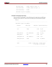
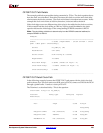
The Source is the starting point of the path. Following the source name is the type of
component. In this case the component is a flip-flop (FF). The FF group also contains the
SRL16. Other components are RAM (Distributed RAM vs BlockRAM), PAD, LATCH,
HSIO (High Speed I/O such as the Gigabit Transceivers) MULT (Multipliers), CPU
(PowerPC), and others. In Timing Analyzer, for FPGA designs the Source is a hot-link for
cross probing. For more information on Cross Probing please see Cross Probing with
Floorplanner.
The Destination is the ending point of the path. See the above description of the Source for
more information about Destination component types and cross probing.
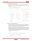
The Requirement is a calculated number based on the time constraint and the time of the
clock edges. The source and destination clock of this path are the same so the entire
requirement is used. If the source or destination clock was a related clock, the new
requirement would be the time difference between the clock edges. If the source and
destination clocks are the same clock but different edges, the new requirement would be
half the original period constraint.
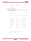
The Data Path Delay is the delay of the data path from the source to the destination. The
levels of logic are the number of LUTS that carry logic between the source and destination.
It does not include the clock-to-out or the setup at the destination. If there was a LUT in the
same slice of the destination, that counts as a level of logic. For this path, there is no logic
between the source and destination therefore the level of logic is 0.
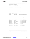
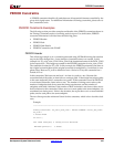
The Clock Skew is the difference between the time a clock signal arrives at the source flip-
flop in a path and the time it arrives at the destination flip-flop. If Clock Skew is not
checked it will not be reported.
The Source Clock or the Destination Clock report the clock name at the source or
destination point. It also includes if the clock edge is the rising or falling edge and the time
that the edge occurs. If clock phase is introduced by the DCM/DLL, it would show up in
the arrival time of the clock. This includes coarse phase (CLK90, CLK180, or CLK270) and
fine phase introduced by Fixed Phase Shift or the initial phase of Variable Phase Shift