148 www.xilinx.com Development System Reference Guide
Chapter 7: MAP
R
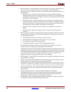
• Blocks trimmed—A trimmed block is removed because it is along a path that has no
driver or no load. Trimming is recursive. For example, if Block A becomes
unnecessary because logic to which it is connected has been trimmed, then Block A is
also trimmed.
♦ Blocks removed—A block is removed because it can be eliminated without
changing the operation of the design. Removal is recursive. For example, if Block
A becomes unnecessary because logic to which it is connected has been removed,
then Block A is also removed.
♦ Blocks optimized—An optimized block is removed because its output remains
constant regardless of the state of the inputs (for example, an AND gate with one
input tied to ground). Logic generating an input to this optimized block (and to
no other blocks) is also removed, and appears in this section.
♦ Signals removed—Signals are removed if they are attached only to removed
blocks.
♦ Signals merged—Signals are merged when a component separating them is
removed.
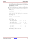
• Removed Logic—Describes in detail all logic (design components and nets) removed
from the input NGD file when the design was mapped. Generally, logic is removed
for the following reasons:
♦ The design uses only part of the logic in a library macro.
♦ The design has been mapped even though it is not yet complete.
♦ The mapper has optimized the design logic.
♦ Unused logic has been created in error during schematic entry.
This section also indicates which nets were merged (for example, two nets were
combined when a component separating them was removed).
In this section, if the removal of a signal or symbol results in the subsequent removal of
an additional signal or symbol, the line describing the subsequent removal is indented.
This indentation is repeated as a chain of related logic is removed. To quickly locate the
cause for the removal of a chain of logic, look above the entry in which you are
interested and locate the top-level line, which is not indented.
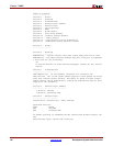
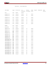
• IOB Properties—Lists each IOB to which the user has supplied constraints along with
the applicable constraints.
• RPMs—Indicates each RPM (Relationally Placed Macro) used in the design, and the
number of device components used to implement the RPM.
• Guide Report—If you have mapped using a guide file, shows the guide mode used
(EXACT or LEVERAGE) and the percentage of objects that were successfully guided.
• Area Group Summary—The mapper summarizes results for each area group. MAP
uses area groups to specify a group of logical blocks that are packed into separate
physical areas.
• Modular Design Summary—After the Modular Design Active Module
Implementation Phase, this section lists the logic that was added to the design to
successfully implement the active module. After the Final Assembly Phase, this
section states whether the logic was assembled successfully.
• Timing Report—This section, produced with the –timing option, shows information
on timing constraints considered during the MAP run.


